


This maintenance tutorial addresses maintenance of the TT250 charging system.
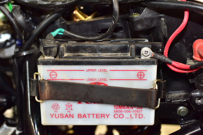
You might have a charging system problem if the battery is dead or the bike is hard to start. It’s more likely this is just a battery problem, so the first thing to do is to check the battery (see the TT250 battery maintenance tutorial).
If you have ruled out a defective battery, the next thing to check is the charging circuit.
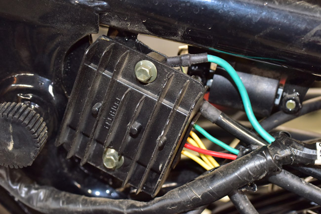
Put a multimeter on the battery and measure the voltage when the engine is revved. It should be between 13.8 and 14.5 VDC. If the voltage is above 14.5 VDC, the regulator is defective and it must be replaced. The regulator is located beneath the fuel tank on the left side of the motorcycle. You will need to remove the seat and fuel tank to gain access to the regulator; the procedure for removing these components is described in other tutorials. If you need a regulator, please call us at 909 445 0900.
If the battery voltage is below 13.8 volts when the engine is revved, more analysis is required.
The next step is to measure the output of the charging system at the crankshaft. We’ll check for AC voltage and resistance. Find the charging circuit harness with the engine running and measure the AC voltage between all three leads. At idle, it should be 12 VDC. With the engine at maximum rpm, it should be 60 VDC.

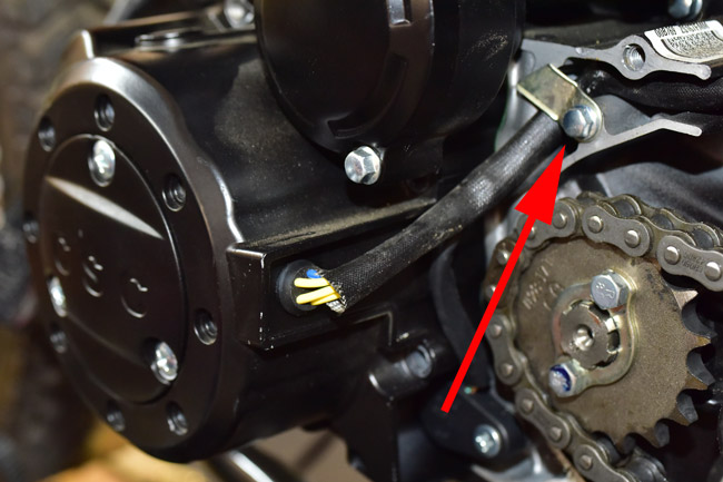
Shut the engine off, disconnect the harness connector shown above, and measure the resistance between all three leads (it should be approximately .5 ohms; anything between .3 ohms and .6 ohms is acceptable). If the resistance is outside the range mentioned above the stator should be replaced. We’ll get into that below.
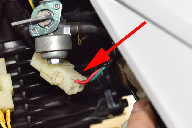
If the charging system from the engine crankshaft (i.e., at the yellow leads discussed above) has appropriate output and resistance, we should next check the output from the regulator. Find the connector plug as shown in the photo below and check the voltage output when the engine is running. If it is below 13.8 VDC or above 14.5 VDC when you blip the throttle, the regulator is defective and it must be replaced.
If it is within the acceptable range (i.e., between 13.8 and 14.5 VDC) but the output at the battery terminals (with the engine running) is outside this range, the problem lies in the circuit between the connector plug and the battery. In this situation, you should check for open circuits, improper connections, or shorts to ground and correct the anomalous condition.
Let’s turn back to the situation described, and that is that the engine is not providing the appropriate output AC voltage or the resistance between the stator leads is too high (as measured at the connector shown earlier). In this situation, there is a problem with the stator, the engine’s internal wiring from the stator, or the rotor. It will be necessary to remove the left engine crankcase cover to inspect and correct the anomalous condition.
Place a drip pan beneath the engine, as oil will escape from the engine during this operation.
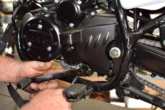
Remove the gear shift lever with a 10mm wrench.
There are several 8mm bolts securing the left engine cover and the countershaft sprocket cover. Remove all of them. Note that the bolts are of different lengths. Take care to note where each bolt is used.
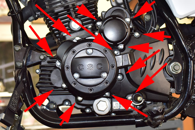
Remove the countershaft sprocket cover.
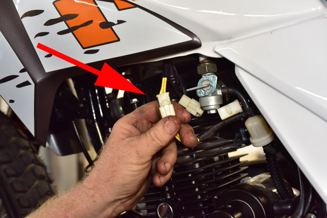
Disconnect the stator harness.
Unbolt the harness retainer from the crankcase.
Remove the starter motor transfer gear cover.
Remove the starter transfer gears. Note their orientation; the smaller gear is closest to the starter motor. Note that there are small shims on either side of the gear cluster; take care not to lose them.
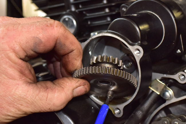
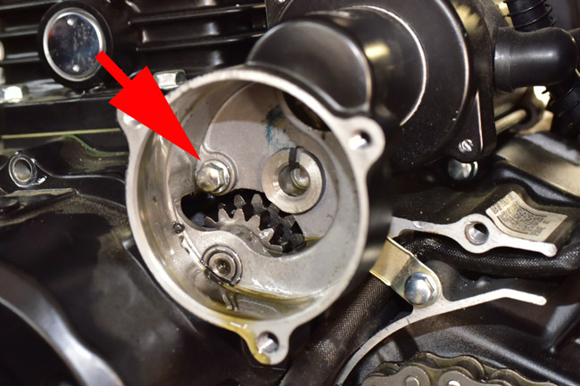
Unbolt the 8mm bolt securing the starter gear transfer case to the crankcase. Note that this bolt is a fully threaded bolt.
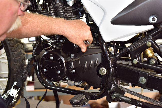
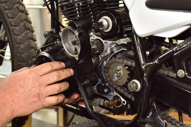
Gently pry the left crankcase engine cover from the engine.
Examine the stator inside the engine cover. If the resistance between the three leads is outside the range specified above, replace the stator. If there is no resistance between any of the leads and ground (this means there is a short to ground), replace the stator. CSC stocks replacement stators; please call us at 909 445 0900 if you need a replacement stator.

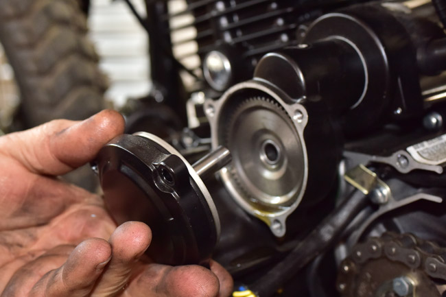
Inspect the rotor. If the rotor is damaged in any manner, you will need to replace it. To remove the rotor, remove the bolt securing the rotor.

Use a rotor pulling tool to back the rotor off of the crankshaft. We sell these; please give us a call at 909 445 0900 if you need this tool.

Assembly is the reverse of disassembly. Apply Loctite to the rotor crankcase bolt and torque the rotor crankcase bolt to 60 N-m. Torque the engine cover mounting and countershaft cover bolts to 9 N-m. Apply Loctite to the stator mounting bolts and torque the stator mounting bolts to 9 N-m.
 SG250 San Gabriel Cafe Racer
 TT250 Enduro