


This tutorial addresses TT250 front and rear brake maintenance.
General Information
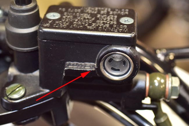
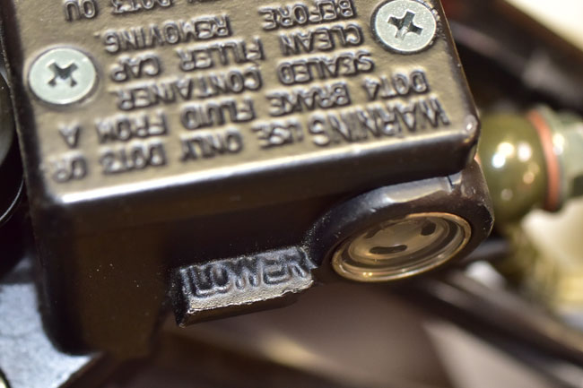
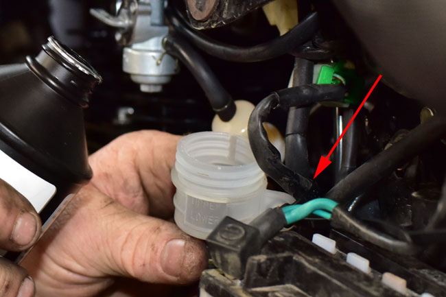
The front brake master cylinder is located on the right handlebar. It has a fluid level indicator on the master cylinder that shows the “low” level. When the front master cylinder fluid level is at the low mark, it is an indication that the front brake pads should be replaced. Do not rely only on this indication; you should check the pad thickness regularly and replace them when they are worn below acceptable limits (to be described below).
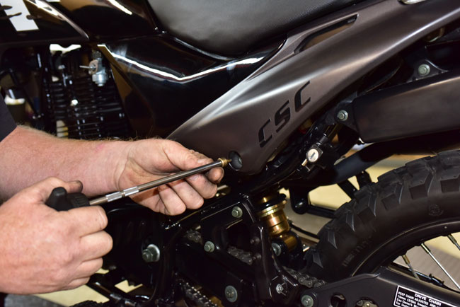
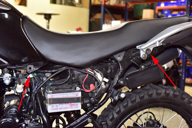
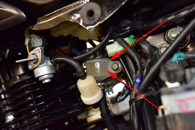
The rear brake master cylinder is located under the seat and behind the carburetor. It is visible from the right side of the motorcycle, but it is easier to check the brake fluid level if the left rear body panel is removed. The left rear body panel is secured by a screw and two grommet snaps, as shown in the photos below.
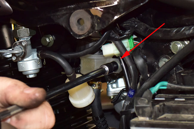
This is the rear master cylinder. Note the upper and lower fluid level marks.
It is possible to check the thickness on the front and rear brake pads without removing the caliper from the motorcycle, but you have to get below the brake calipers to do so. It is better to remove the caliper to better see the pads.
Front Brake Pad Inspection and Replacement
The front brake caliper is located on the left side of the motorcycle.
Loosen the front brake caliper’s two 5mm Allen pins.
Remove the caliper’s two 8mm mounting bolts and then remove the caliper from the front rotor and fork. You should not remove the hydraulic brake line or loosen it.
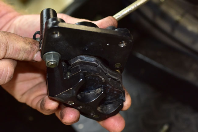
Completely remove the caliper’s two 5mm Allen pins, and remove the two brake pads.
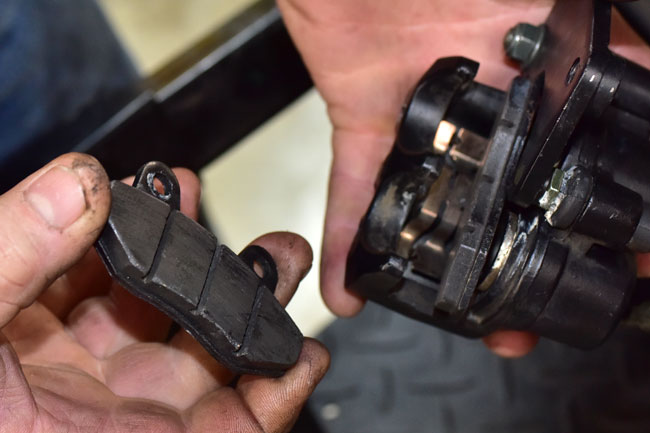
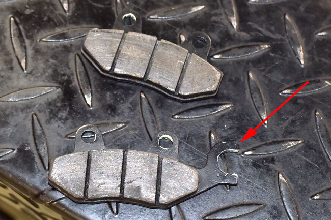
The front brake’s pads are interchangeable left to right (the rear brake’s pads are not). Note that the brake pads have wear grooves machined into the pad surface. These are the three vertical slots you see in the photo above. When the pads are worn on either pad such that the wear indicators are no longer visible, replace the pads with new pads. We keep these in stock, so call us at 909 445 0900 if you need to order a pair. Note that it is normal for the front brake pads to wear much more quickly than the rear brake pads.
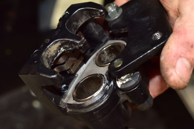
Push the caliper pistons all the way into the caliper.
Assembly is the reverse of disassembly. Install new front pads , install the two 5mm Allen pins, place the caliper over the rotor, and install the two caliper mounting bolts. The 5mm Allen pins should be torqued to 3 to 5 ft-lbs. The caliper mounting bolts should be torqued to 15 to 18 ft-lbs.
Rear Brake Pad Inspection and Replacement
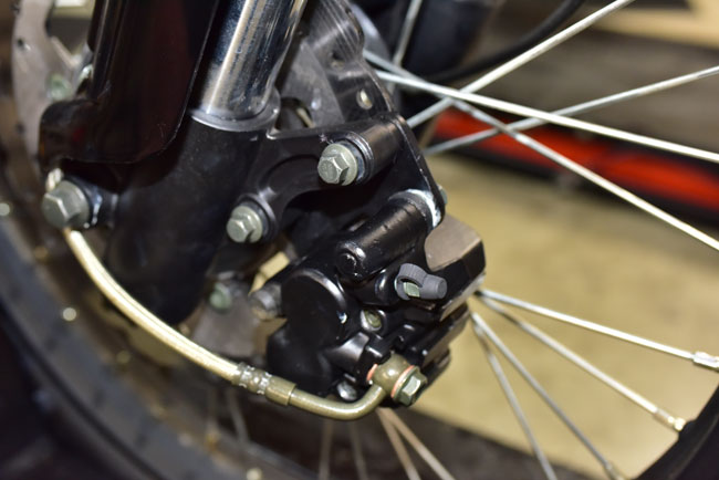
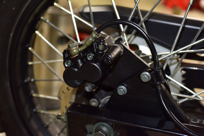
The rear brake caliper is located on the right side of the swingarm.
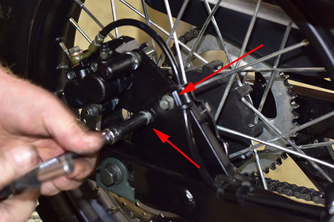
Loosen the rear brake caliper’s two 5mm Allen pins.
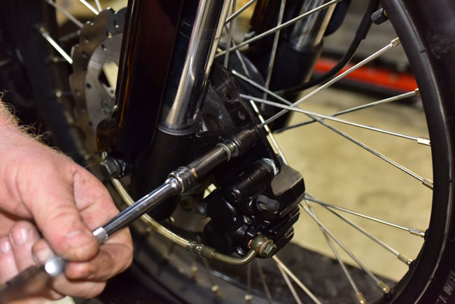
Remove the caliper’s two 8mm mounting bolts and then remove the caliper from the swingarm. You should not remove the hydraulic brake line or loosen it.
Completely remove the caliper’s two 5mm Allen pins, and remove the two brake pads.
Note that unlike the front brake, the rear brake’s calipers are different. The one with the extension on it goes on the inside of the rotor (the side closest to the spokes).
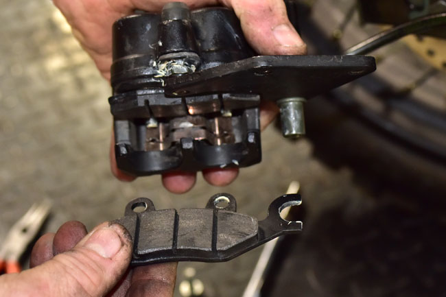
When the pads are worn on either side such that the wear indicators are no longer visible, replace the pads with new pads. We keep these in stock, so call us at 909 445 0900 if you need to order a pair. Note that it is normal for the front brake pads to wear much more quickly than the rear brake pads.
Assembly is the reverse of disassembly. Push the caliper pistons all the into the caliper. Install new rear brake pads , install the two 5mm Allen pins, place the caliper over the rotor, and install the two caliper mounting bolts. The 5mm Allen pins should be torqued to 3 to 5 ft-lbs. The caliper mounting bolts should be torqued to 15 to 18 ft-lbs.
Front and Rear Brake Rotor Inspection
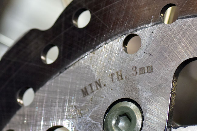
Both the front brake and rear brake rotors are 4mm thick when new. If either rotor thickness drops below 3mm, the rotor should be replaced.
The front and rear brake rotors are each retained by Allen head bolts that take a 6mm drive. These should be torqued to 22 ft-lbs. Take care when removing these for the first time; they are Loctited in place at the factory and it is easy to strip the Allen drive socket (we recommend heating the head of the bolt first to soften the adhesive). We keep replacement rotors in stock; if you need a new rotor please call us at 909 445 0900.
Flushing and Replacing the Brake Fluid
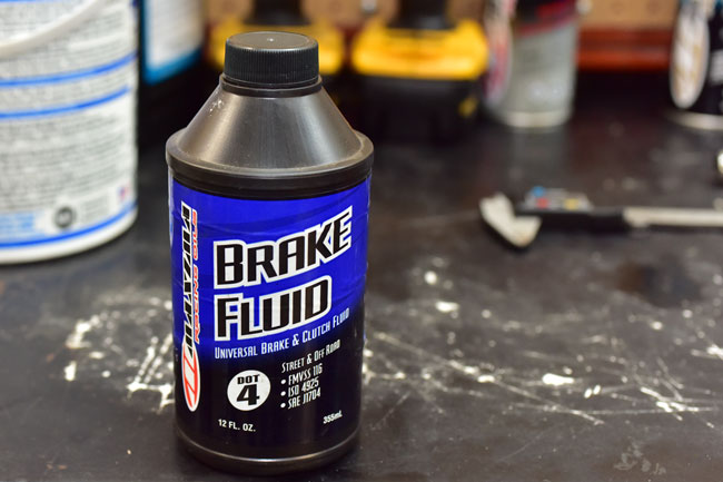
It is a good idea to bleed the brakes every year, and to flush and replace the brake fluid every two years. Use only DOT4 brake fluid. We sell brake fluid suitable for use in your TT250 motorcycle; if you need brake fluid please call us at 909 445 0900.
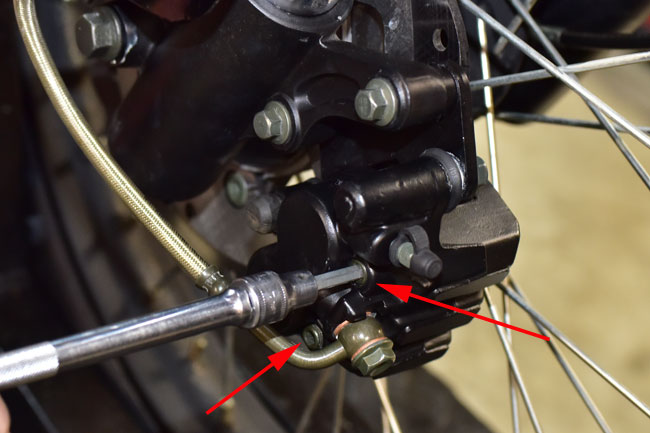
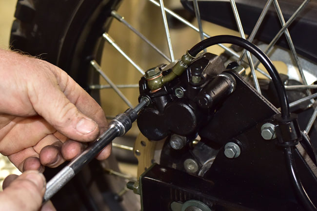
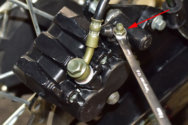
To drain the brakes, open the master cylinder. Attach a hose to the caliper bleed port and route it to a suitable container. Open the caliper bleed port with an 8mm wrench and allow the brake fluid to drain. Note that the drain hose is not shown in the photo below to allow clarity in identifying the caliper bleed port.
After draining the brake fluid, add fluid to the master cylinder and bleed the brakes as described below.
Bleeding the Brakes
To bleed the brakes, attach a hose to the brake caliper bleed port and route it to a suitable container.
Open the master cylinder. The front brake master cylinder cover is removed with a Philips head screwdriver. On the rear brake master cylinder, it is best to gain access by removing the left rear body panel (as outlined earlier in this maintenance tutorial), unbolting the master cylinder from the frame, and temporarily securing the rear brake master cylinder in a vertical orientation with a zip tie.
Open the caliper bleed port with an 8mm wrench while applying the brake lever, and before releasing the brake lever, close the bleed port with the 8mm wrench. It’s important not to allow the bleed port to remain open while releasing the brake lever or you will suck air into the system. Repeat this open-the-bleed-port, apply-the-brake-lever, close-the-bleed-port, add-brake-fluid process until the master cylinder is full. Reinstall the brake master cylinder cover. For the rear brake master cylinder, reinstall the rear brake master cylinder in its proper location and reinstall the left rear body panel.
Prior to taking the motorcycle on the street, operate it slowly and apply the brakes several times. Once the system is appropriately pressurized, you’re ready to ride!
 SG250 San Gabriel Cafe Racer
 TT250 Enduro