


The topic today is how to adjust your CSC Cyclone’s valves, but before we dive into the details, a bit of background is in order. We’ll start with a discussion of the CSC Cyclone’s engine, then we’ll talk about what valve adjustment is and why it is necessary, and then we’ll cover how to do the adjustment on the Cyclone.
We used our EPA test mule bike for this adjustment because it had about 8,000 miles on it, and we wanted to get a feel for where the valve gaps were after accumulating that kind of mileage. It’s also the bike to which we applied our camo theme (just in case you were wondering about the paint job).
Your CSC Cyclone has a high performance, single overhead cam, 4-valve engine. There are two exhaust valves and two intake valves. The reason the engine has four valves is that it provides for more flow through the engine, which is another way of saying the engine makes more power than it would if it only had two valves.
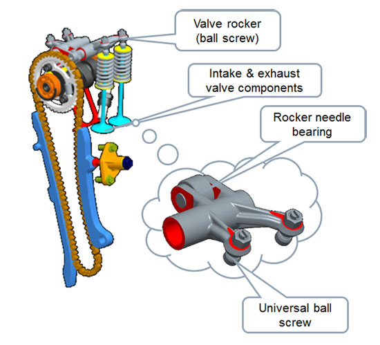
Cyclone valve train
The Cyclone has a single camshaft with two lobes, and two rocker arms. One rocker arm actuates both intake valves; the other rocker arm actuates both exhaust valves. The cam’s lobes are what actuate the rocker arms. As the cam lobe lifts the rocker arm, the rocker arm pivots on its shaft. The rocker arm has one arm that follows the cam lobe up and down, and two arms that actuate its two valves.We want the engine to open the intake valves to admit the fuel/air mixture, and we want the engine to open the exhaust valves to expel the exhaust. When the engine is at the top of its compression stroke, we want all of the valves closed. That’s because we want to compress the fuel air mixture, ignite it, and then allow the resulting high combustion pressures to drive the piston down. If any leakage occurs around any of the valves while this is occurring, the engine will lose power and it could “burn” a valve if the combusting fuel/air mix escapes around the valve while it is still burning.
When engineers design an engine, they want it to do the above, but they have to account for the thermal expansion that occurs as engine temperature increases during normal operation. In order to compensate for this thermal expansion, the engineers design in a gap in the cam lobe/rocker arm/valve train. As the engine warms, this gap approaches zero, and everything works the way it is supposed to.
You might be wondering at this point why the engineers can’t just build in a gap and then leave everything alone. The problem with that is that the valves close against a seat every time they go up and down. Think of the large diameter of the actual valve, and the cylinder head port against which it forms a seat. Here’s the problem: As the valve pounds against the seat zillions of times as the engine runs, very small amounts of deformation occur in both the valve and the valve seat. It’s microscopic, but it grows over time as the engine runs.
As the wear described above increases, it has the effect of reducing the valve gap (i.e., the clearance built into the valve train to account for the thermal expansion as the engine warms up). What happens is that as this wear occurs, the valve actually moves higher into the cylinder head and the valve gap decreases. If this wear goes beyond acceptable limits without adjusting the valves, the valve gap grows smaller and smaller. Ultimately, this wear will result in the valve being held off the seat when combustion occurs. This is bad, because when this condition exists, hot burning gases escape around the valve sealing area. Ultimately, these burning gases will destroy the valve and the seat. That’s what happens when we “burn a valve.”
If the above sounds really bad, relax. We avoid it by adjusting the valves. All we are really doing is keeping the gap in the valve train within an acceptable range over the life of an engine. As the valve and the valve seat wear, we keep everything adjusted so that when the engine is at operating temperature we still form a good seal around the valve seat. That’s the whole idea behind this valve adjustment business.
Different engines use different approaches for adjusting the valves. Your Cyclone engine uses the best approach for easy maintenance and high performance: It uses a threaded adjustor shaft with a lock nut to set and lock the valve gap. These adjustors are located in the ends of the rocker arms that interface directly with the valve stem. You can see these in the sketch above, and in the photos we’ll be showing you shortly.
So, with all that theory behind us, let’s consider what we’re going to do here:
- We want to gain access to the valve rocker arms and their adjustment screws.
- We want the engine to be at a point in its rotation such that the rocker arm is on the cam’s base circle. This means the cam is not actuating the rocker arm. We want the engine to have the piston at (or very near) top dead center, which means the valves should be closed (which is another way of saying the rocker arm is on the cam’s base circle).
- With the engine in this position, we want to loosen the threaded adjustor lock nuts, we want to set the valve gaps to the specified gap of 0.04mm to 0.06mm, and we want to tighten the lock nuts to lock the threaded adjustors at this gap.
- When we’ve completed the above, we want to put everything back together.
Got that? Okay, here we go….
Most of the work in adjusting the valves is associated with just getting access to the adjustors. The adjustment operation (once we have access) takes only a few minutes.
When you adjust the valves, you have to start with a cold engine. Dead cold. Let your Cyclone cool down completely. Don’t cheat on this part. I always let the bike not run for a day. If it’s even a bit warm from running, your adjustment will be wrong, and all of your work will be for nothing. Let your Cyclone cool down completely.
Remove the rear seat with the key lock, the front seat with its two 8mm bolts, all of the bodywork around the fuel tanks, and the fuel tank. Like I said above, this is the bulk of the labor. It works a lot better if you’ve run the fuel tank down (so it won’t be as heavy). Make sure you don’t spill any fuel, and make sure you put the fuel tank in a location where there are no ignition sources. And make sure you don’t scratch any of the body work. This may seem like a lot of work, but it’s pretty common on modern motorcycles, and after you’ve done this the first time, you’ll find that this all comes off in about 15 or 20 minutes.
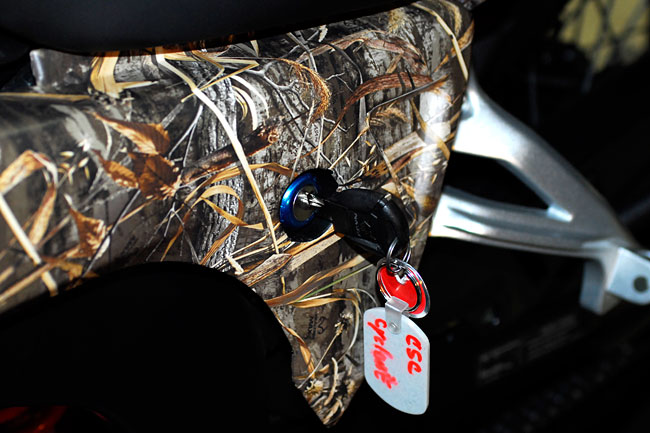
Use the key to unlock the rear seat
Remove the rear seat
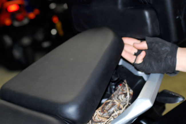
With the rear seat off you can next remove the forward potion of the seat
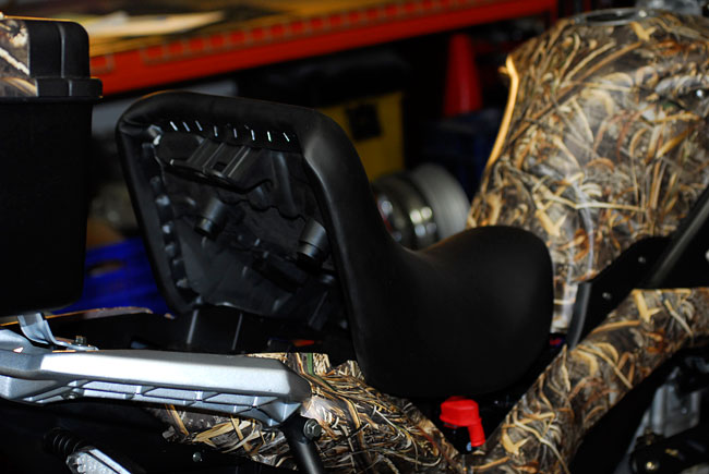
Remove the forward part of the seat
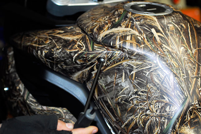
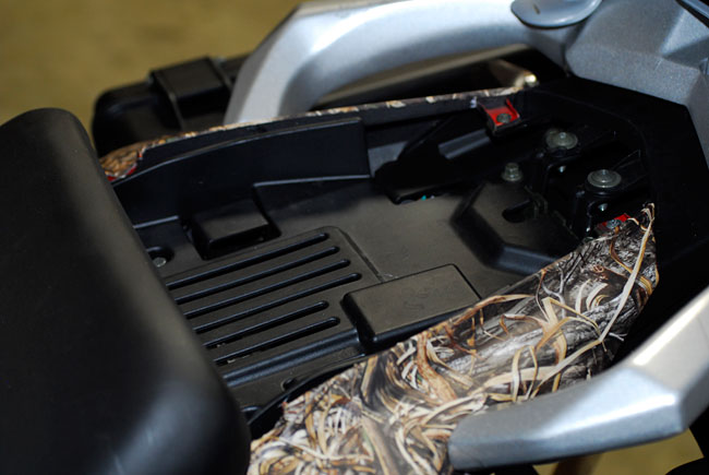
The body work around the tank comes off
The tank also has to be removed to gain access to the valves
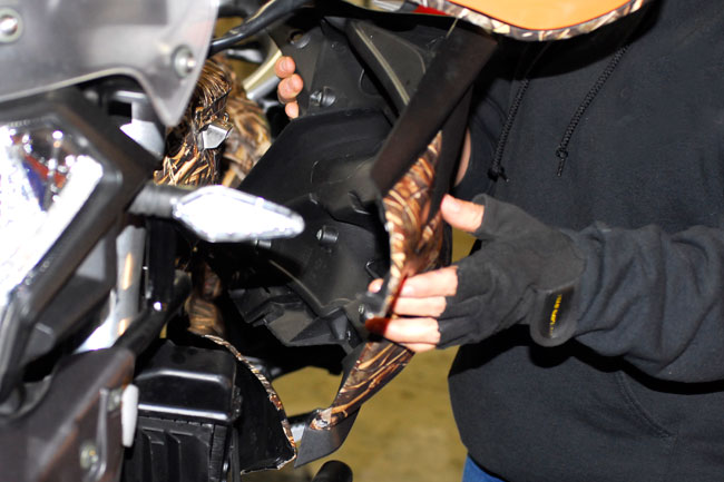
All of the body panels around the tank have to be removed, both on the right side…
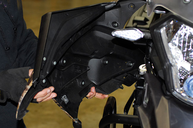
…and the left.
The next step is to unbolt the Cyclone’s twin radiators. You don’t have to disconnect the hoses or remove the radiators; you just want the radiators to be loose so that you’ll have access to the valve covers on top of the cylinder head.
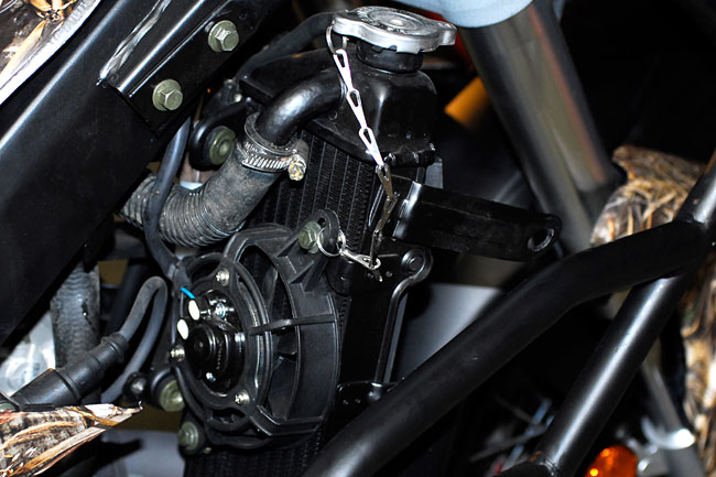
Unbolt the radiators but leave them in place…don’t disconnect the hoses
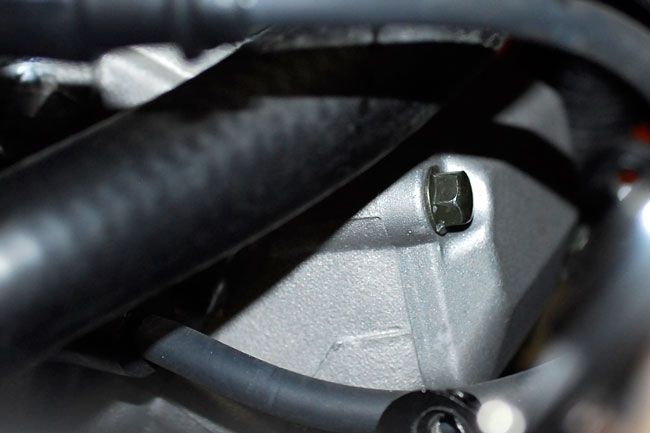
After you’ve done the above actions, remove the access port on the left side of the engine crankcase. It comes off with a 10mm Allen wrench, and inside of it, you’ll see another Allen receptacle. This is connected directly to the crankshaft, and it’s what we’ll use to manually rotate the engine.
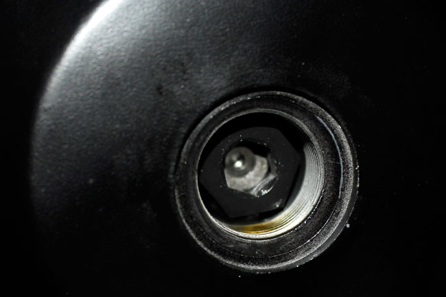
The crankshaft access port
Next, remove the view cap on the left front of the engine crankcase, just forward of the port described above.
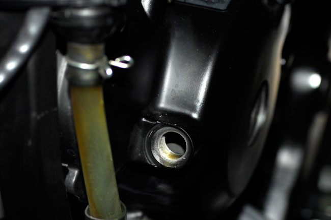
This is the view port for viewing the stator cover…more on this later
The next step is to remove the spark plug wire and then the spark plug.
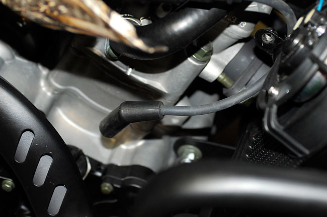
Pull the wire off of the spark plug
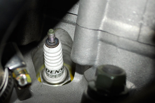
Remove the spark plug
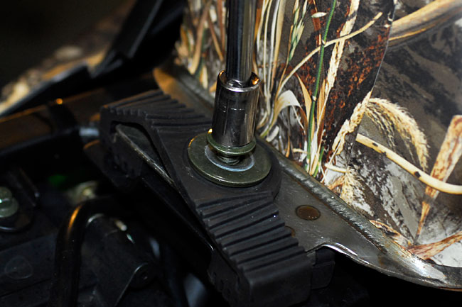
Finally, remove the intake and exhaust valve covers. Each cover is secured with two 8mm bolts. Note that the covers are not interchangeable.
The valve covers are secured with two 8mm bolts
The rear valve cover is removed with a ratchet and an extension; the front valve cover is removed without the ratchet extension
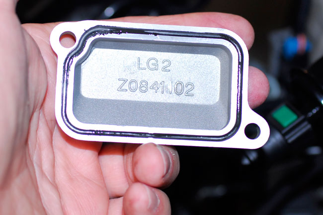
The intake valve cover and the exhaust valve cover are not interchangeable
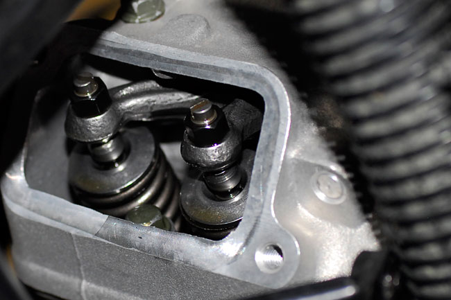
What we’ve been working to get to…the valves
You know, when I got to this point on the Cyclone, I was pretty impressed. The casting and machining quality on these engines is very, very high. This is a quality product.
Once the bike is “opened up” for valve adjustment, the next step is to position the piston at top dead center. With the motorcycle in neutral, insert a 10mm Allen wrench through the crankcase port and turn the crankshaft until the alternator scribe line is aligned with the index register in the viewing port, as shown below.
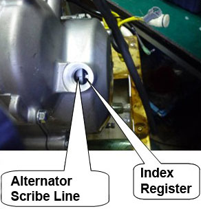
Finding the scribe line on the alternator cover may be a bit challenging, as you have to get down low enough to see it. Wear safety glasses when you do this; you don’t want to get oil spitting into your eye! It’s further complicated by the fact that even though you’ve removed the sparkplug, the sparkplug hole into the combustion chamber is tiny and it’s difficult for the air to escape when you turn the crankshaft. You’ll still feel a little compression as you rotate the crankshaft. Don’t worry; it’s a normal occurrence on the Cyclone engine.
The alternator scribe line doesn’t have to be exactly in the center of the viewing port. What we are really interested in accomplishing with this action is to get the rocker arms on the cam profiles’ base circle (that is, off the lobes). We want this so that the valves are closed (they’re not being held open). We want the valves closed when we adjust the gap.
Once we have positioned the engine as described above, we can insert a feeler gage between the valve and the threaded adjustor. This gap should be 0.04mm to 0.06mm. If the 0.06mm leaf slides in too easily, the valve gap is too large. That can result in noisy valves (valve tap). If the 0.04mm shim does not slide into this gap, the valve gap is too tight. Ride around like that too long and you’ll burn a valve (as described earlier).
The shim goes right where you see it in this photo
Personally, a little bit of valve tap noise is okay with me (“tappy valves are happy valves”), because it tells me the valves are fully closing. If there’s too much gap, though, the valves may not be lifting far enough off the seat when it is supposed to, and power will be reduced. But a little bit of noise is okay, as long as the power is there.
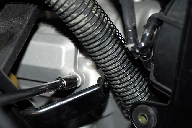
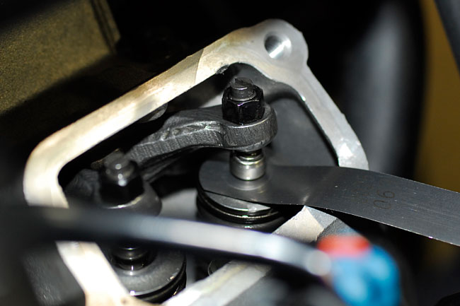
The valves are adjusted by loosening the lock nut on each threaded adjustor (like a lot of nuts and bolts on the Cyclone, the lock nut is an 8mm). Back the threaded adjustor out a bit with a flat blade screwdriver (see the photo below), insert the 0.06mm shim, and then screw in the adjustor until it’s just snug against the shim. You want there to be just a bit of drag on the shim when you slide it in and out. It’s the kind of thing you get a feel for after you’ve done it a couple of times.
When the adjustor is where you want it to be, tighten the lock nut. Then check the gap with the shim again. Sometimes I’ll have to do this two or three times to get the gap to be where I want it after tightening the lock nut. It’s all part of the process. Take your time and get it right.
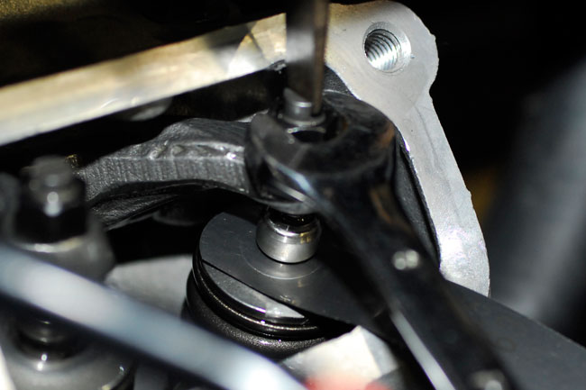
Loosening the lock nut and adusting the threaded adjustor to get the required valve gap
You need to do the same adjustment (and set each valve at the same gap) for all four of the Cyclone’s valves. When I think I’m done, I crank the engine through a couple of revolutions by hand, and check the valve gap again. It’s usually right where I want it, but if it’s not, I’ll repeat the above process until it is.
What you’ve just accomplished can set you back a thousand bucks or more on some motorcycles when you take them to the dealer to have the valves adjusted. You’ll probably take two or three hours to do this job the first time you do it, but after you’ve done it a couple of times, you’ll get it down to under an hour.
Folks, that’s it. All you need to do now is put everything back together, and get out and ride!
 SG250 San Gabriel Cafe Racer
 RX1E Electric Motorcycle
 TT250 Enduro