


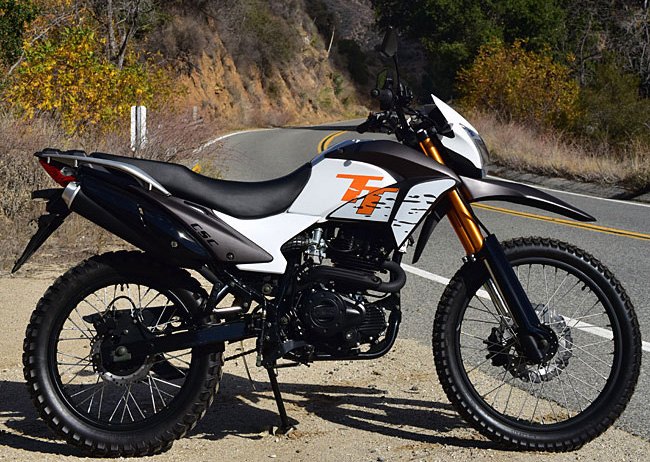
This tutorial addresses TT250 clutch replacement. The TT250 uses a wet multiplate clutch.
Drain the engine oil into a suitable container. Refer to the TT250 engine oil change tutorial for instructions on how to do this.
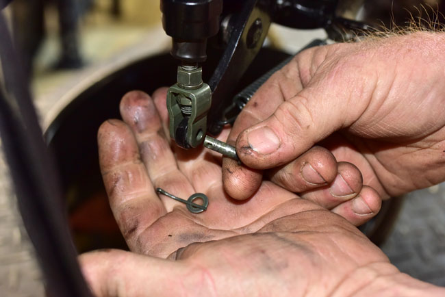
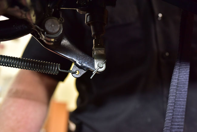
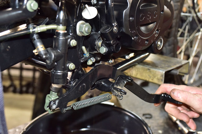
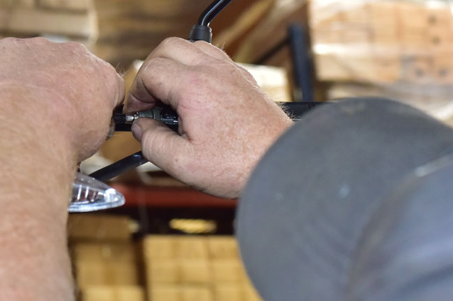
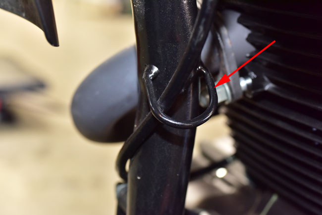
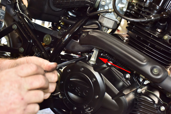
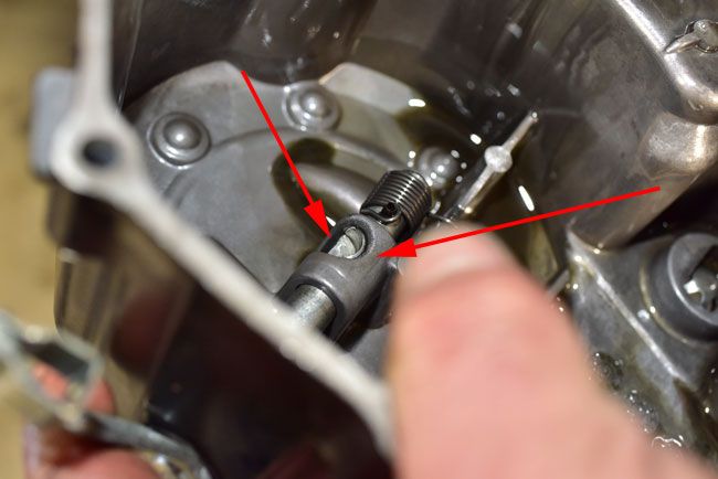
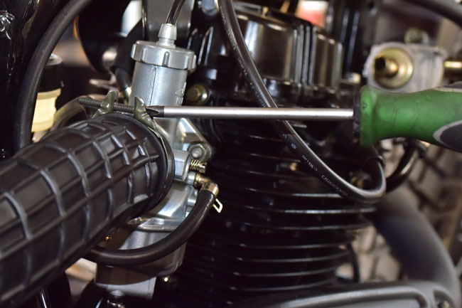
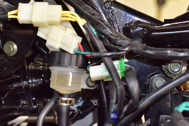
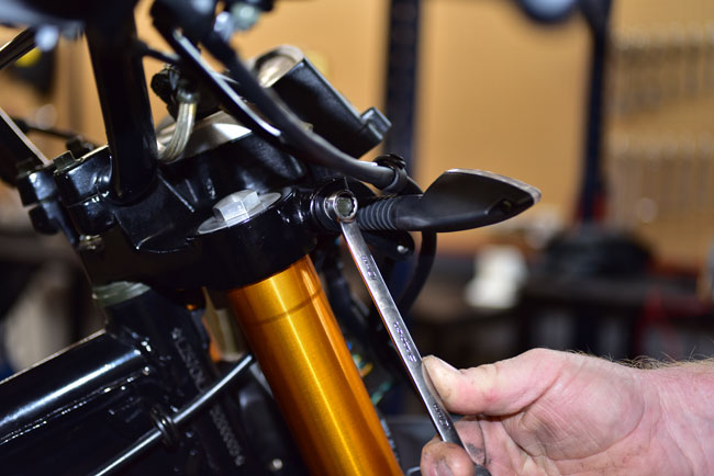
Disconnect the rear brake lever from the rear master cylinder by removing the cotter pin and pulling the shaft out. This will allow rotating the rear brake lever out of the way to allow removing the right engine case.
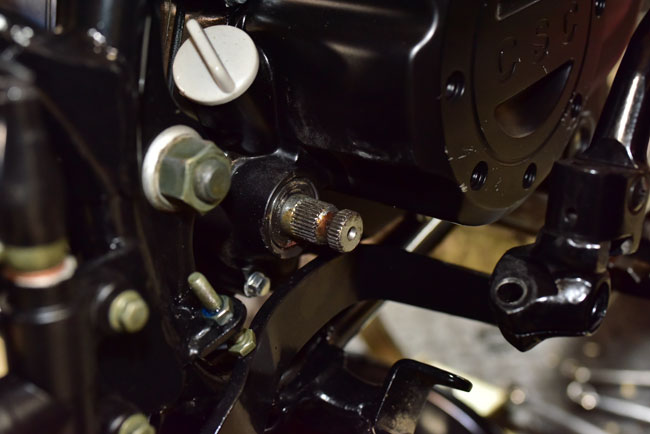
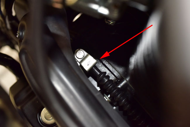
Remove the 13mm bolt securing the kick start lever and remove the kick start lever.

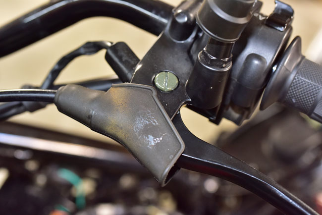
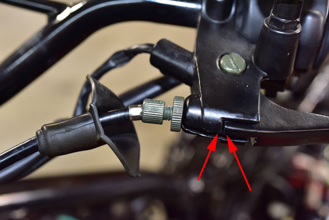
Loosen the handlebar clutch lever cable adjustor by screwing it all the way into the clutch lever casting.
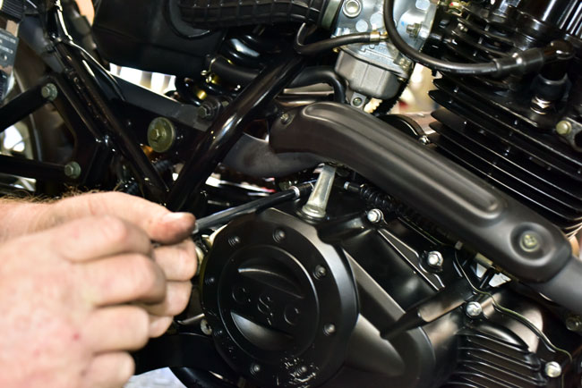
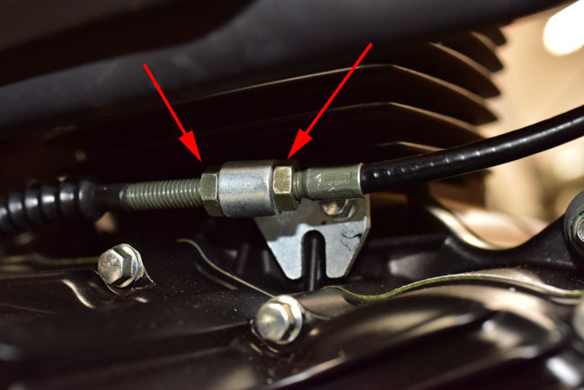
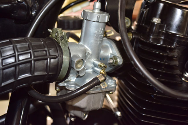
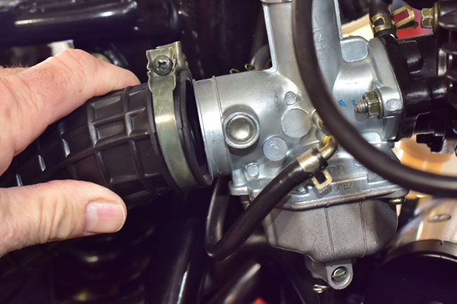
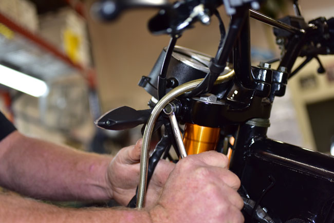
Disconnect the clutch cable at the engine end.

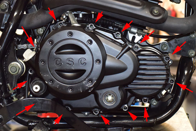
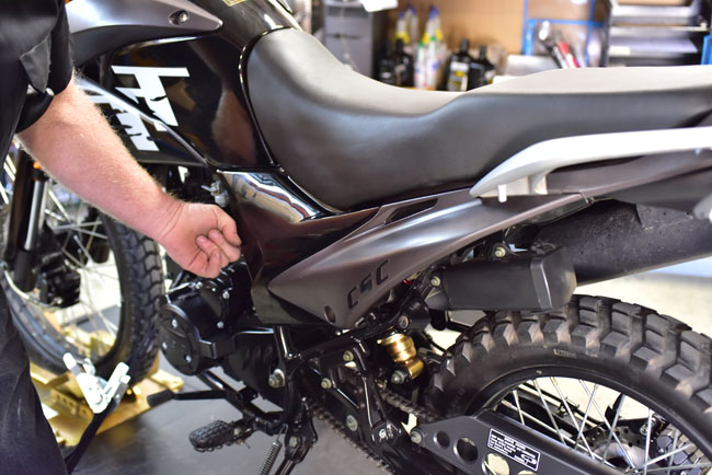
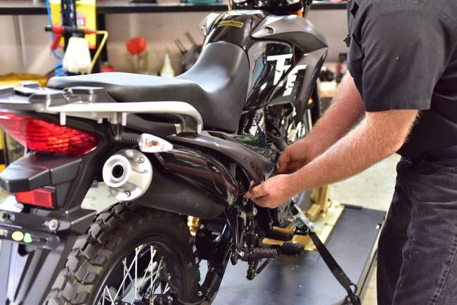
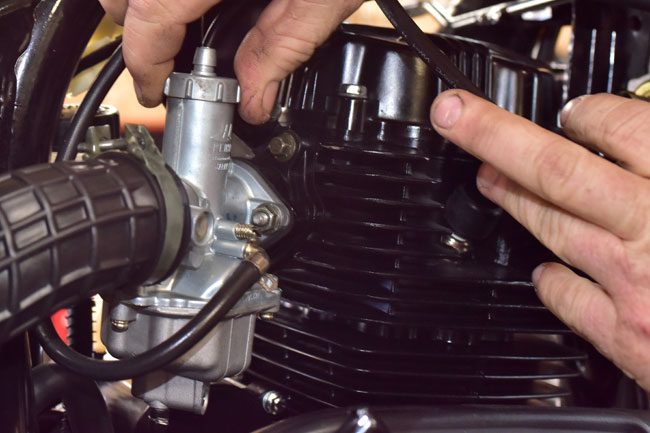
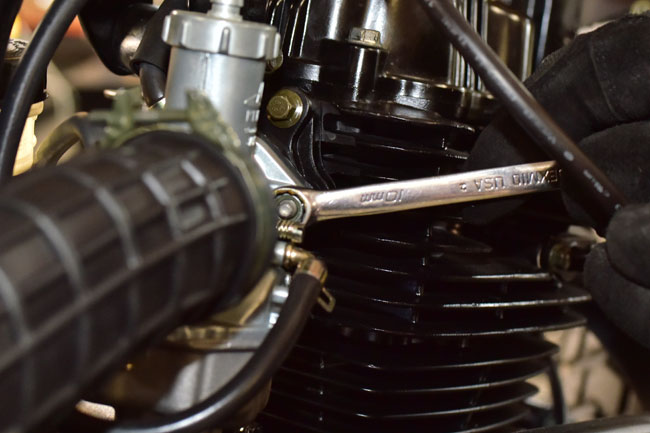
Remove the 13 10mm bolts securing the right engine cover to the engine.
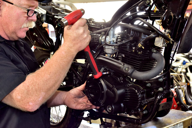
Tap the right engine cover lightly with a soft mallet to loosen it.
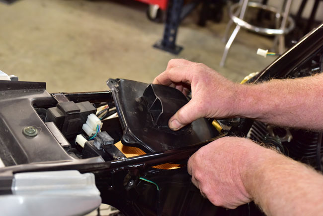
Remove the right engine cover.
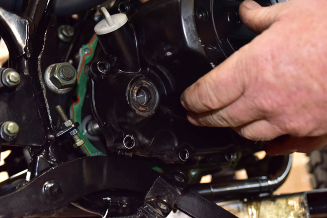
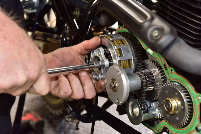
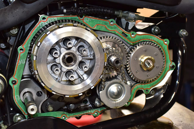
At this point, you will see the engine internals on the right side of the engine. These components are labeled here for reference during the remainder of this tutorial.

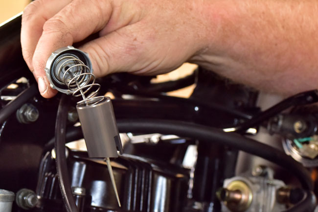
Remove the clutch actuation rod and bushing.

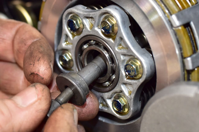
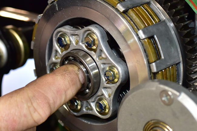
Remove the clutch throwout bearing. If this bearing is worn or does not operate smoothly, replace it with a new bearing.
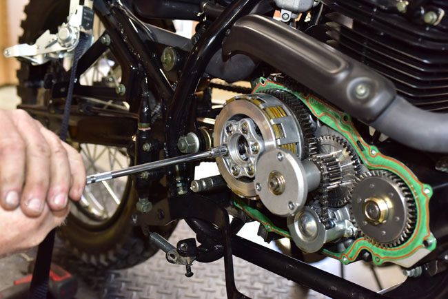
Remove the six clutch bolts in an even pattern by unscrewing each bolt a few turns at a time. Do this in a criss cross pattern to allow the clutch hub to back out evenly.
Remove the clutch hub to expose the clutch springs.
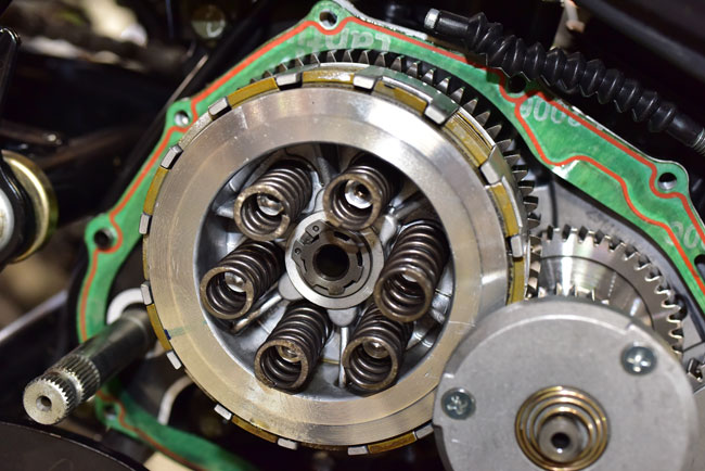
We recommend replacing the clutch springs when replacing the clutch.
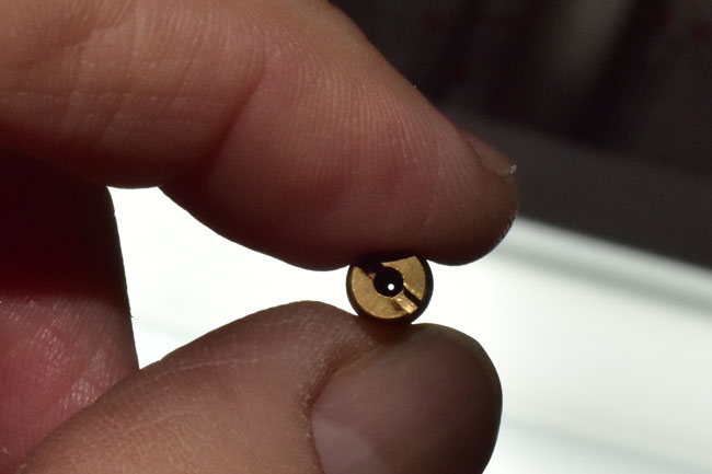
Remove the Circlip that secures the clutch inner basket.
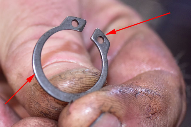
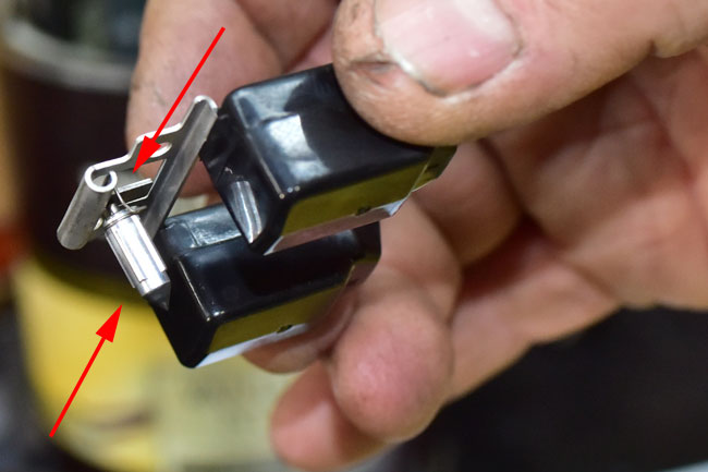
For reference during reassembly, the Circlip has a sharp-cornered edge and a radiused edge on opposite sides. The sharp edge should face away from the motorcycle during reassembly.
This is the sharp edge.

This is the rounded edge.
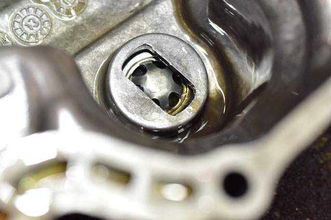
To remove the rest of the clutch components, it is necessary to remove the centrifugal oil cleaner.
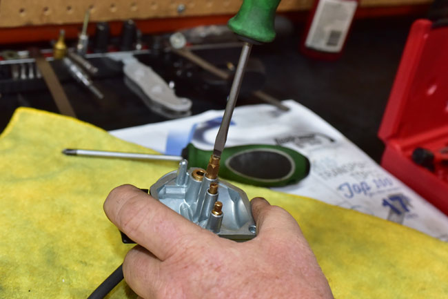
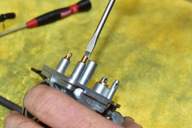
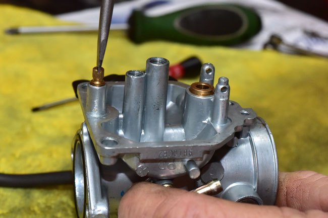
Unscrew the three Phillips head screws on the centrifugal oil cleaner.
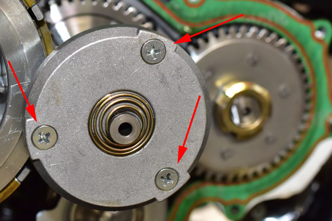

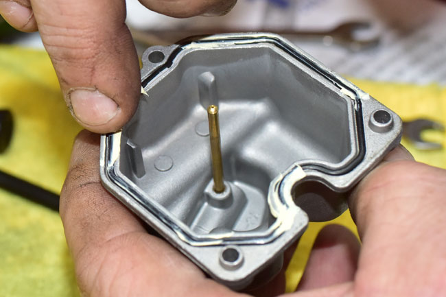
Remove the centrifugal oil cleaner cover.

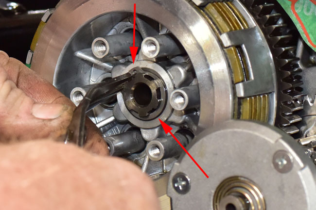
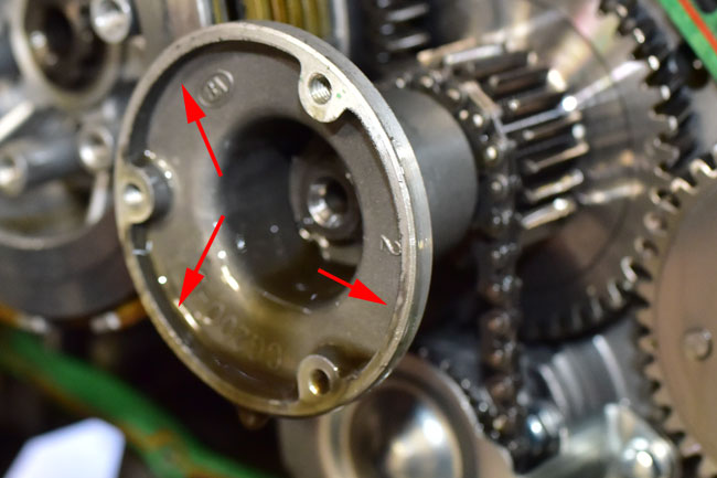
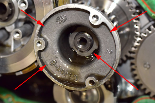
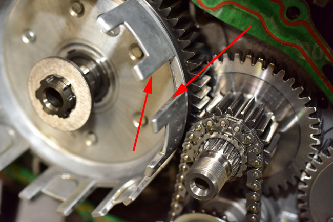
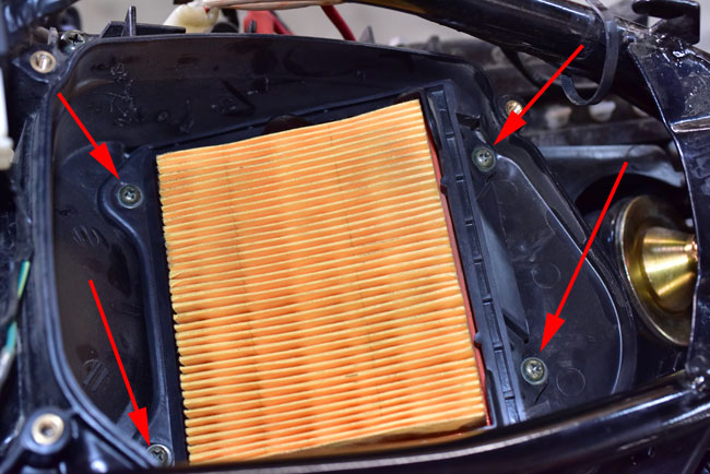
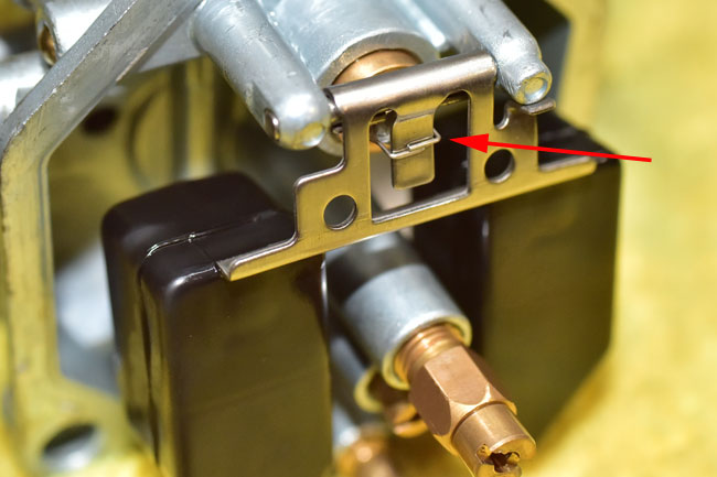
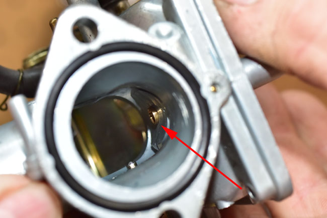
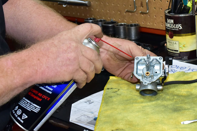
The engine used for this tutorial only had a couple of hundred miles on it, so there was no dirt or sludge in the centrifugal oil cleaner. On a motorcycle with much higher mileage, packed sludge will accumulate around the inner periphery of the centrifugal oil cleaner in the areas shown by the red arrows below. Scrape this sludge out and wipe the interior of the centrifugal oil cleaner clean.
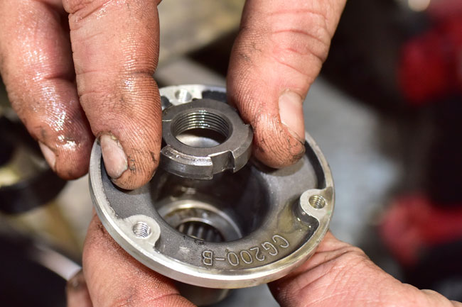
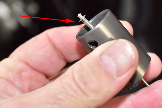
The inner portion of the centrifugal oil cleaner is secured by a castellated nut. This nut is shown by the lower red arrow on the right in the photo below.
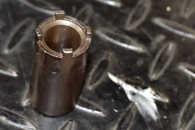
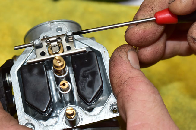
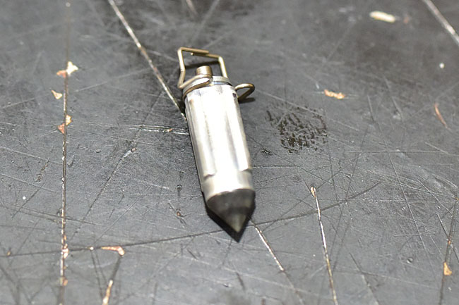
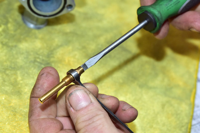
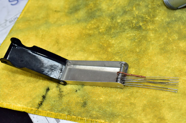
Use a castellated nut driver like the one shown below to remove the nut.
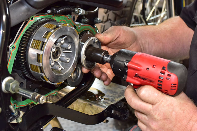
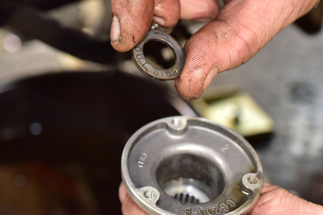
Remove the castellated nut.
There is a washer underneath the castellated nut. This washer is labeled to show which side should face out.
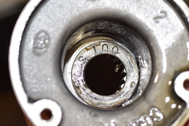
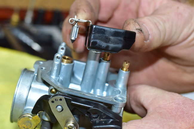
Pull the inner portion of the centrifugal oil cleaner off of its shaft.
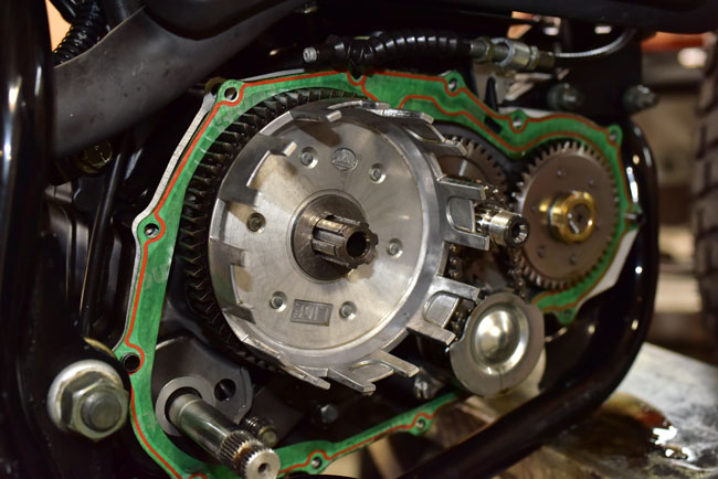
At this point (after removing the inner portion of the centrifugal oil cleaner), the clutch inner basket and clutch components can be removed.

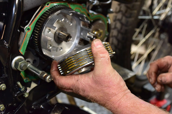
The clutch consists of six fiber plates and five steel plates as shown below. The fiber plates are all the same. The steel plates are all the same. The fiber plates are the outer plates on both sides of the clutch assembly. The plates alternate in this order:
- Fiber plate
- Steel plate
- Fiber plate
- Steel plate
- Fiber plate
- Steel plate
- Fiber plate
- Steel plate
- Fiber plate
- Steel plate
- Fiber plate
CSC stocks the clutch plates and the clutch springs. Please call us at 909 445 0900 to order these components if you need them.
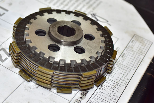

Inspect the clutch inner basket for any discontinuities in the notches on which the clutch plates translate. If the clutch inner basket has surface discontinuities or excessive wear, replace it.

Similarly inspect the clutch outer basket for any surface discontinuities or excessive wear. Replace the clutch outer basket if necessary.
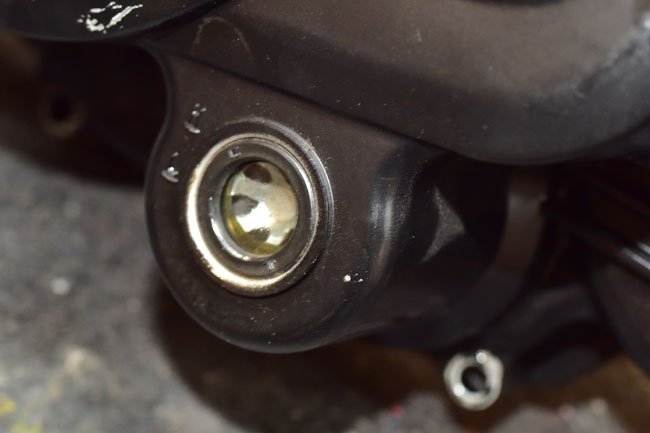
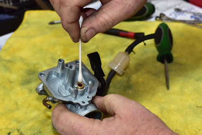
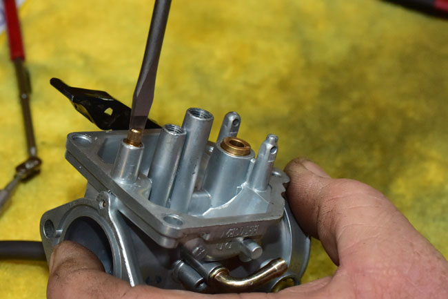
The kick starter seal should be replaced if the engine cover is removed.
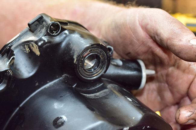
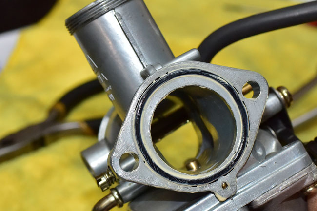
Inspect the oil viewing port. If any external leakage is evident, replace the oil viewing port seal.
The oil viewing port can be pushed out from the inside of the engine cover.
Before installing the new clutch plates, soak them in motorcycle oil for 24 hours. If you don’t do this, you may ruin the new clutch.
Assembly is the reverse of disassembly. Use a new engine cover gasket. Torque the clutch derby bolts to 5 ft-lbs. Torque the engine cover bolts to 15 ft lbs. Torque the kick start lever bolt to 35 ft lbs. Torque the centrifugal oil cleaner castellated nut to 60 ft lbs.
After installing all components, adjust the clutch as explained in the TT250 clutch adjustment tutorial.


 SG250 San Gabriel Cafe Racer
 TT250 Enduro