Hey, we just received this cool 360-degree video from our good buddy Stephen in Tennessee…seems there are a lot of people riding the RX3 two up!
Thanks for sending the video to us, Stephen! We’re glad you and your wife are enjoying the RX3.

Hey, we just received this cool 360-degree video from our good buddy Stephen in Tennessee…seems there are a lot of people riding the RX3 two up!
Thanks for sending the video to us, Stephen! We’re glad you and your wife are enjoying the RX3.
Wow, where to begin…
How does 381 miles, crossing Baja’s Vizcaino Desert, and doing it all on 12 RX3 motorcycles sound to you?
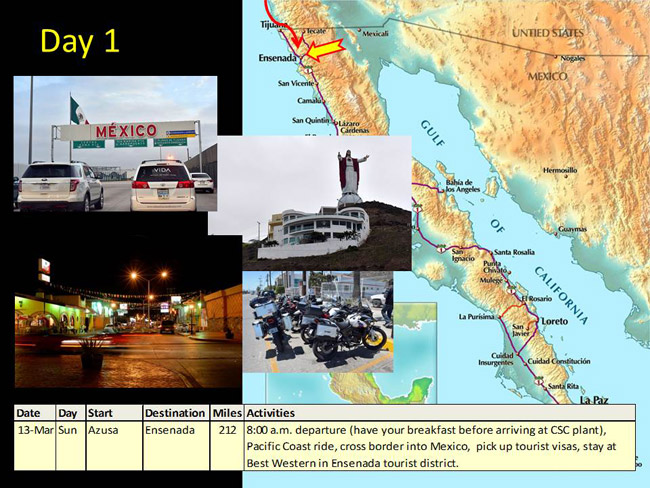
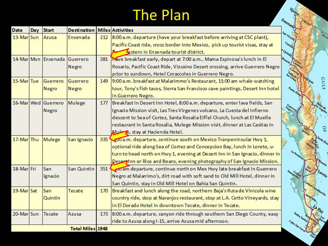
Let me back up a bit. It was just two nights ago that we had our departure dinner at CSC. As part of the pre-ride safety briefing, I assembled a PowerPoint presentation to bring everybody up to speed. While I was riding across Baja today, I thought it might be a good idea to include the slides I presented to our team at that dinner to help you understand what we are doing. Backing up, this was the slide for yesterday, when we rolled down from Azusa to Ensenada…
Okay, so that was yesterday. Here’s what we did today…
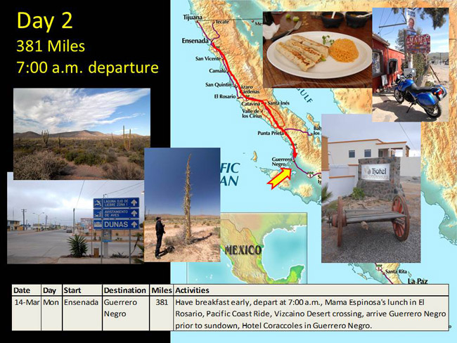
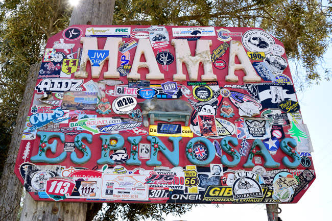
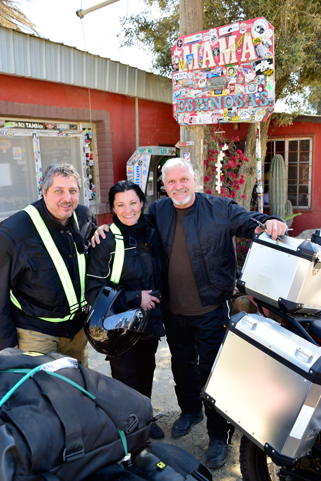
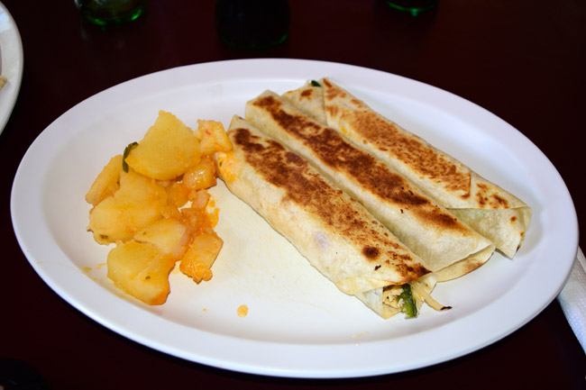
It was an intense riding day today. We were up at 5:00 a.m., we found a 24-hour restaurant in Ensenada, and as planned, we were on the road at 7:00. We covered about 130 miles before stopping for lunch in Baja’s iconic restaurant, Mama Espinosa’s.
Here’s a photo of Fathi, Doina, and Willie. Fathi and Doina are doing this ride two-up on Fathi’s RX3.
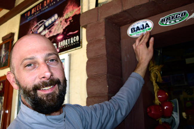
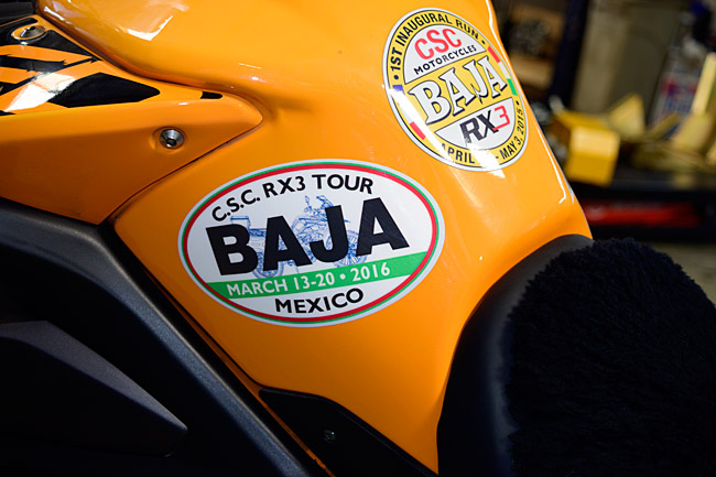
Good buddy Dave, adding a CSC Baja 2016 decal to the zillions adorning the walls in Mama Espinosa’s.
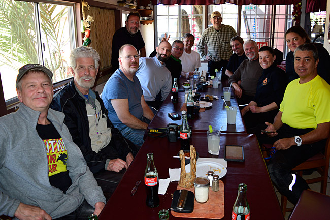
Here’s a shot of the crew at lunch today. From left to right, it’s Dan, Dan, Mark, J, Dave, Gary, Keith, Mike, Fathi, Willie, Doina, Sara, and Juan.
My favorite at Mama Espinosa’s – their chicken burritos!
We stopped to visit the ruins of the Misión San Fernando Rey de España de Velicatá. It was built in 1769 and what you see below is all that’s left of it. Getting out there involved some pretty gnarly roads, and quite a few folks dropped their bikes in the soft sand.

You might think dropping your bike would be a source of embarrassment, and when it happens, it probably is. But that changes quickly and predictably. The guys and gals at dinner tonight were actually bragging about who dropped their bike the most. I think we’ve had something like 10 bikes go down so far (and this is only Day 2). It’s pretty funny listening to the conversations at dinner. When someone drops their bike, the first reaction is “did anybody see me do this?” By dinner time (and with a few Tecates), the stories and the laughter start. We sure have a good bunch of people on this ride.
Here’s Baja Mike’s battle-scarred bike…

We had a great dinner this evening. I opted for the house fish filet dinner, which was sea bass, and it was delicious.

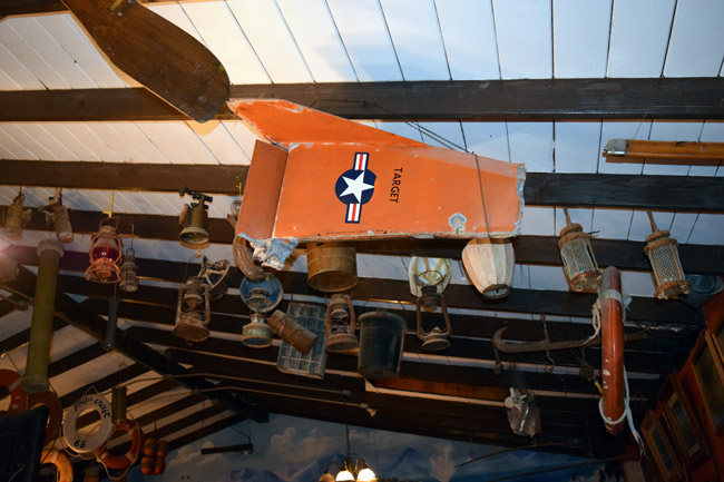
If you look at the map of Baja, you’ll see that the peninsula forms a hook jutting out into the Pacific Ocean here in Guerrero Negro. Because of that, a lot of stuff drifting down from points north washes up on the Guerrero Negro shores, and the restaurant at Malarimmo’s has a bunch of it hanging from their ceiling. It’s a cool display.
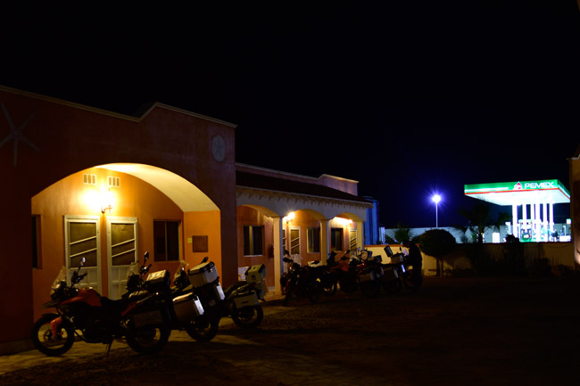
After dinner, we walked back the hotel. I snagged this shot of the bikes put away for the evening…
As I said, it was an intense day. Tomorrow is laid back. We’re not having breakfast until 9:00, and then we’re going whale watching at 11:00. I’m going to help Juan change his oil earlier in the morning. We’ll get back from whale watching around 3:00, and then we’re just going to hang around Guerrero Negro. If everything goes well (and I know it will), I’ll have some great whale photos for you tomorrow. Maybe we’ll even see the Great White Whale. We’ll see.
That’s it for now. I’m beat. It was a good day and I’ll sleep well tonight.
Like always, stay tuned!
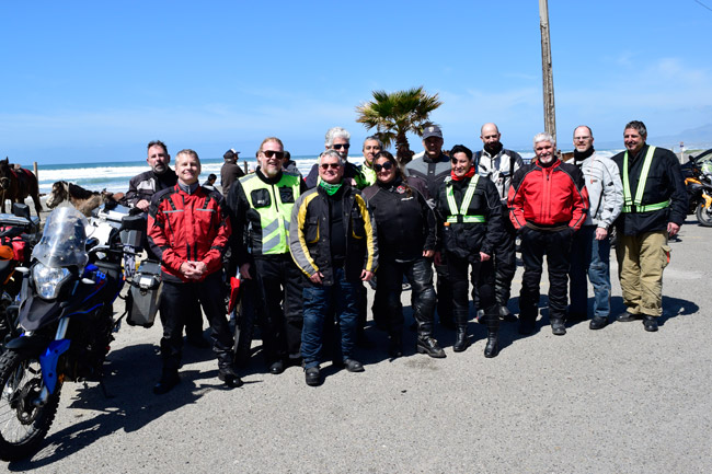
We’re out here living large, folks! It was wheels in the wells at 8:00 a.m. this morning when we rolled out of Azusa. It was good day…an easy 212-mile ride, and we are spending the night in Ensenada. I was able to grab a few photos of the 13 people on this adventure ride and a few other things as well…enjoy!
Good buddy Fathi, who is riding two up with his wife Doina. I’ll get some more photos of her in the next day or two…
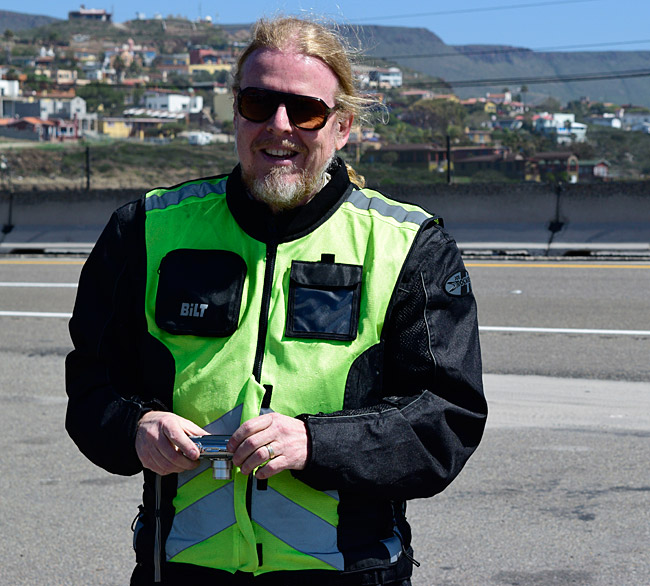
Good buddy Mike, with Baja in the background…
Good buddy Dan, another member of the CSC RX3 Colorado contingent. There are four guys from Colorado on this ride!
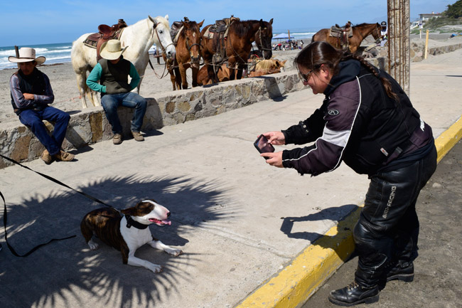
Good buddy Sara, making a new friend along Mexico’s Pacific coast…
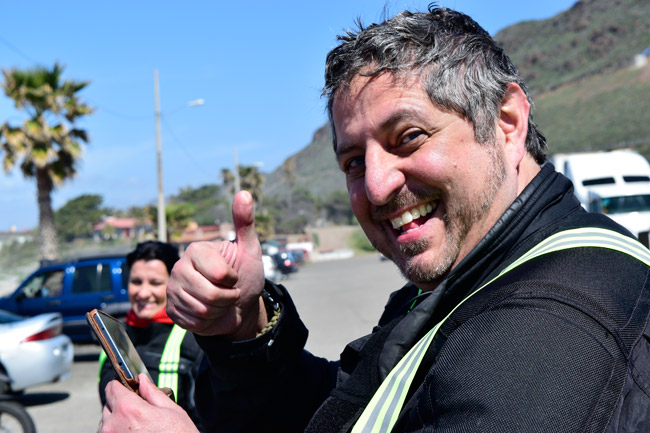
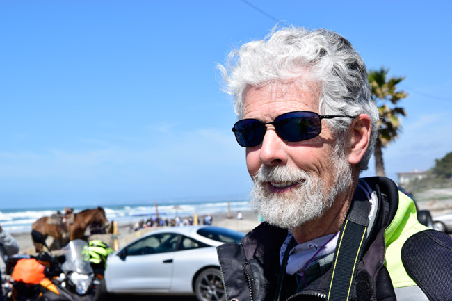
Good buddy Keith, who rode with us on last year’s CSC Baja ride…
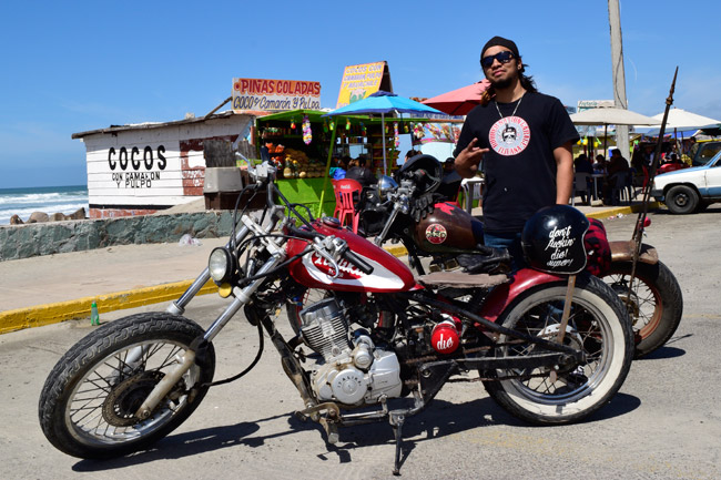
This is Sayed, a local guy with a cool CG-engined chopper. We talked bikes for a while and he let me take a photo…
The crew enjoying what can only be described as a glorious day. The riding was wonderful today. 12 RX3 motorcycles, the Pacific Ocean, Mexico…it just doesn’t get any better! No, wait…it’s going to be even better tomorrow!
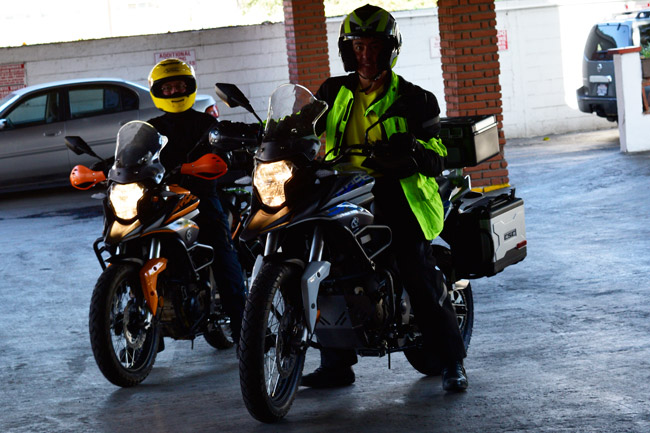
A couple of our RX3 pilots in the hotel parking area.
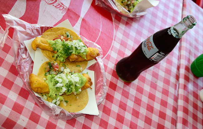
Wow, street tacos! This guy knows his business. Lunch was delicious.
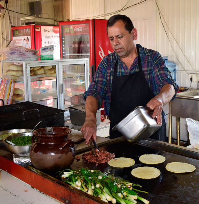
My incredible fish taco lunch…all $3.25 of it!
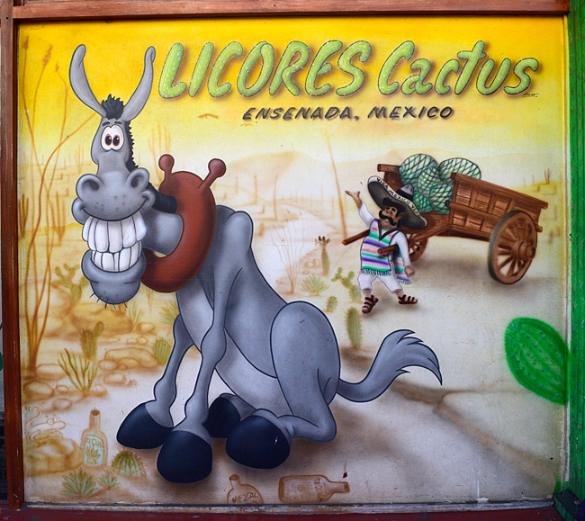
I saw this sign along the street in Ensenada and I grabbed a photo…
Good buddy Mike one more time…he’s been thinking about buying the new CSC RC3, and he thought he would try the more aggressive riding stance…
My good buddy J, enjoying a beer I never heard of until tonight and one with a name I can’t remember. After putting the bikes away for the night we enjoyed awesome appetizers and a beer or two. Good times, my friends!

We’re going to be on the road at 7:00 a.m. tomorrow, and we’ll make Guerrero Negro by nightfall. It’s going to be a long, 381-mile day, but like any day in Baja, it’s going to be fun. We have an exceptionally good group of people on this ride and I am enjoying it immensely.
Stay tuned…more to follow!
Wow, there’s lots happening here! Folks started arriving for the Baja Ride a couple of days ago, and you can feel the excitement here in the CSC plant. Discussions on centered on what to bring, how much air to put in the tires, and all that goes with a big ride like this one. It’s going to be a hoot! Here’s our good buddy Fathi with his RX3, fully equipped with Wolfman luggage…
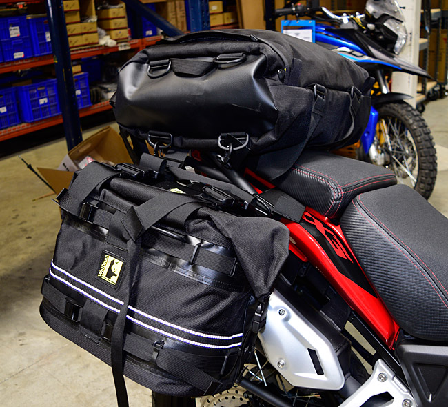
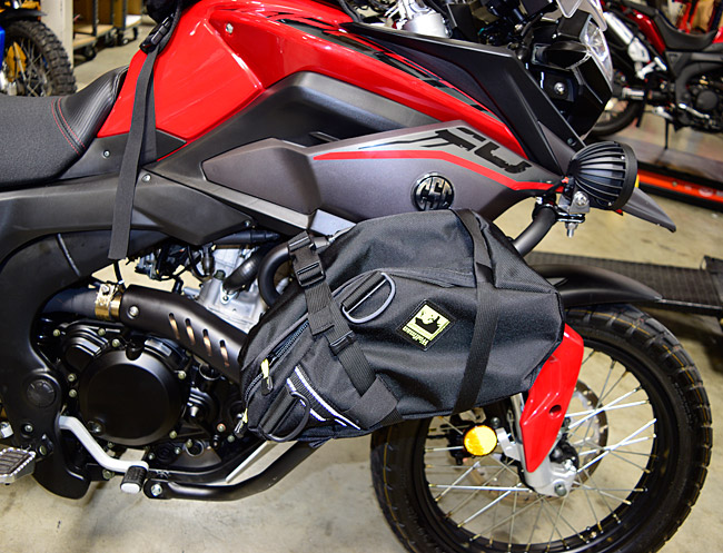
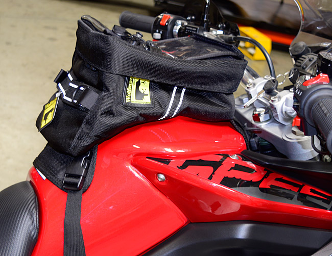
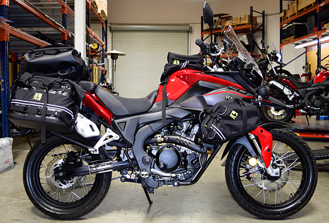
Fathi’s bike looks good, and I like the idea of the soft luggage. Baja will give it a good workout. It’s going to be fun, my friends.
We’re having an Italian dinner here at the plant tonight for the folks who are going on the Baja run, and immediately after dinner, we’ll be going over the route for each day, our safety and riding practices, where we’re staying, and more. Here are just two of the slides from what we’ll be covering after dinner…

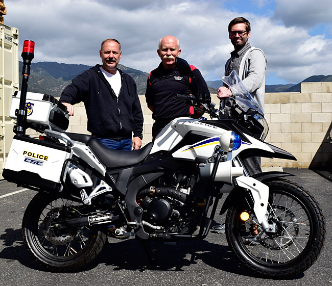
More cool stuff…another CSC RX3-P police bike went out this morning, headed to an agency in northern California! That’s Sergeant Jack, Gerry, and Ryan a short while ago, with the San Gabriel Mountains in the background.
I’m having a lot of fun with the guys who are arriving for the Baja ride. They are almost universally reviewing what they are bringing and then asking me if they should bring anything else. As soon as they ask, I tell them about having an anti-venin kit…
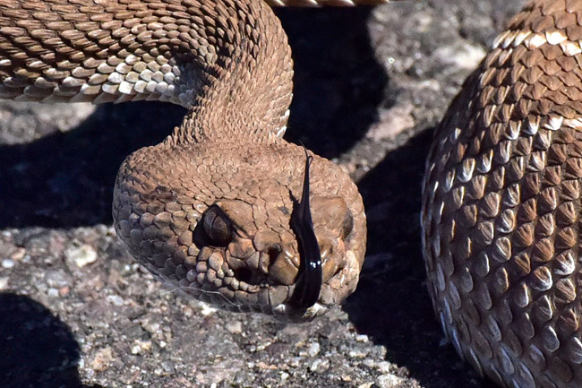

I’m just joking, of course. But so far, everyone has taken me seriously for at least a few seconds.
One more cool thing…you guys know I like playing with things that go bang (especially old military rifles, when they were real weapons with blued steel and wooden stocks). Early this morning I scored an original Polish Mosin M44, manufactured in the 1950s, and never issued! This is a brand new 60-year-old rifle!
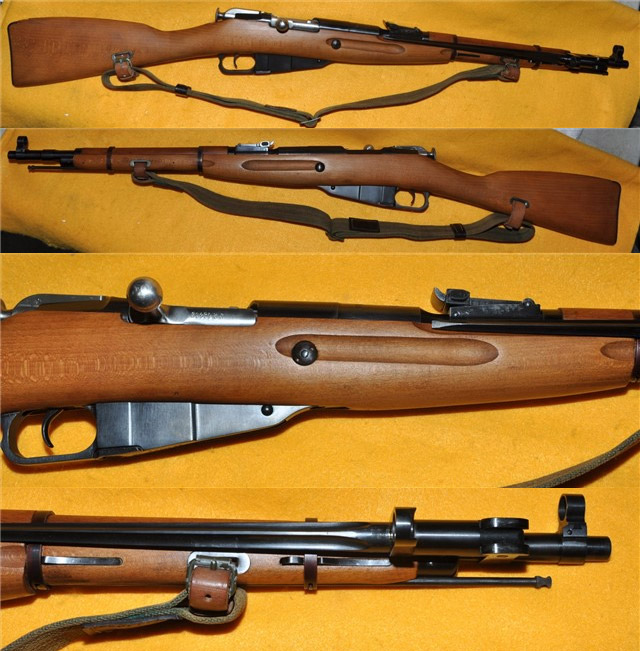
I’ll be taking possession of that rifle sometime around the first week in April, and I’ll let you all know how it shoots.
Ah, Baja beckons. Onward in our search for the great white whale!
Good news for all you folks who have been patiently waiting on your new RX3 motorcycles…the EPA has released the bikes from their temporary hold at the port in Los Angeles. The Feds checked them out and, not surprisingly, they found the bikes met all requirements. The 2016 RX3s start arriving at the CSC plant on Monday.
Please don’t bombard us with phone calls…all hands are on deck and we’ll call you as soon as your bikes are ready.
Me? I’m getting ready for Baja. Keep an eye on the blog…we’ll be posting more as the trip progresses and as I find Internet connectivity!
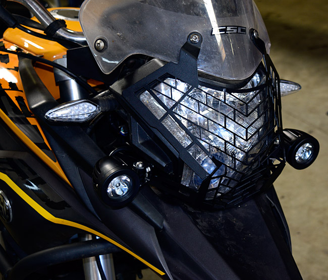
My good buddies Derek and Lupe installed the new headlight grill and spotlights on my RX3 this morning…
…and I did a bit of work on the bike more in keeping with my mechanical skills…
Sunday. Wheels in the wells. We’ll be on the road. Stay tuned.
And boy oh boy, it’s going to be fun! I rolled up into the San Gabriels on my RX3 this afternoon, and I had a little fun with Photoshop afterward…
Ah, chaos theory. It holds that some things are impossible to predict or control, such as the weather, the stock market, and the reactions of things to seemingly unrelated events. The concept is that a butterfly flaps its wings in South America, and through a series of related (but impossible to predict) events, the price of fuel drops in Alaska. You get the idea.
So, wind back the clock a few years to some criminal engineer and his cohorts (and I use those words intentionally) at Volkswagen making a decision to incorporate engine management software that changes their diesel engines’ operating parameters when VWs are tested for emissions compliance. It’s illegal as hell, yet they did it. It apparently went on for years.
Last year, VW got caught. This year, the EPA is running flat out checking everyone for emissions violations (including CSC). Our latest shipment of RX3s was pulled (along with vehicles from other manufacturers) for random emissions checks. Thanks, VW, for creating the conditions that resulted in delays for us and for our customers. If we could find a way to do it, we’d send you an invoice for the $1000/day storage fees we’re paying while the EPA does its job, and for the delays in getting the bikes to folks who dearly want them. It’s all due to your criminal activities, VW. Rest assured, the odds of any of us ever buying a VW are zero. Zip. Nada. Squat. I’ll walk before I ever get into a VW.
We don’t fault the EPA for this. They are doing their jobs, and their jobs are important. This emissions stuff is serious business. I personally have a breathing disorder aggravated by air pollution. To be blunt, I am furious about what VW did. If it was up to me, I’d make VW give a full refund to anyone who ever bought one of their criminally-designed cars and then I’d ban VW from ever selling another vehicle of any kind in the US.
That’s enough of my rant. The impact of VW’s criminal activity to us is that our latest RX3 shipment has been placed on hold in Customs while the EPA does its tests. We’re in a line of vehicles being tested. We only learned this in the last few days, and we still don’t know when our bikes will be released. The EPA can take up to 30 days to do this. We may get the bikes today, or we may get them at any time within 30 days of the time they pulled the shipment. It’s frustrating, we’ve called everyone we know who could possibly help us, but there’s no getting around it.
We’re confident the bikes are compliant, so there are no worries there.
When we found out why the bikes were delayed, we notified our customers. Here’s one of the many emails we have received in response. This one is from our good buddy Mike…
Hey all,
I know you are all amazingly busy, prepping for the arrival of the bikes, preparing to head out to Baja, servicing owners and doing all things great. I just wanted to take a moment and say THANK YOU.
I actually just started riding this year, October, first time, ever…at 48. I bought a KLR250 Super Sherpa. I was never a cruiser or speed bike kind of guy. I discovered the world of Adventure bikes and began the hunt for my next bike. I was probably going to get the KLR650 but I was scared to death of the weight. I do a lot of solo adventuring, and was planning on rolling cross country to explore. The tons of videos I saw with people struggling to pick up their bikes, made me think twice. I also saw the Long Way series and saw the struggles a heavy adventure bike caused. I was miffed.
My buddy and I (who subsequently bought a TT) have become outright enthusiasts, and neither of us can remember who discovered CSC first. However, I can say, that my excitement has not diminished. Discovering the 2015 RX3 was mind-blowing for me. I watched every minute of footage, read every review, and everything fell into place for me. In my desperation, I started absorbing all the videos of the sister bikes throughout the world, the AKT, the Honley, the M1insk etc…all to fill the void. THEN you announced the 2016 and the deal was made.
Between the updated blog, the forums, and reading Joe Berk, I have developed a true sense of awe at CSC the company and more importantly, CSC the people. I am a buddhist, and I am always on a quest for “good humans” and you are some of the best.
I don’t want to kill your day with my annoying fan-boy email. I really just wanted to say…”THANK YOU” to each and everyone at CSC Motorcycles for helping an old guy discover a new world. Thanks for being a truly HUMAN company, with good people. Thanks for bringing a great product to America and for responding to your patrons, fans and even detractors in a considerate and human way.
I don’t mind waiting, because I am confident it will be worth whatever wait it is but I appreciate the information.
Have a great day!
Michael
Order #11 (Orange is the fastest color, Joe)
Folks, hang in there. We know those of you waiting for your RX3s are frustrated. We are, too. The bikes will be here soon. We’ll keep you posted.
I just received an email from my good buddy Juan pointing to this exciting video he created of our 5000-mile Western America Adventure Ride!
This is good stuff, folks!
And that, of course, is the opening line of Herman Melville’s timeless classic, Moby Dick.
You’re probably wondering…where is he going with this?
Folks, I can’t make up stuff this good. An albino whale has been spotted in and around Scammon’s Lagoon, and that’s where we going to be in about 10 days on the CSC Baja Run…
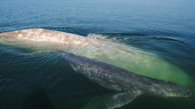
No kidding. I just read this story, and if you want to read it, the link is here. This white whale has been named Gallon of Milk. That name’s not quite as catchy as Moby Dick, but hey, who’s complaining? This is cool stuff. Gallon of Milk is going to be where we’re going whale watching. Wowee!
Imagine that: A white whale. If I had a Spanish gold doubloon I’d nail it to my RX3 and promise it to the RX3 rider who spots the great white whale first. That’s what Ahab did in Moby Dick.
Amazing events, my friends. And we will see whales. Up close and personal, just like you see in this video below I shot on a previous trip…
It’s going to be a fun ride, folks. Just don’t call me Captain Ahab. Or Ishmael.
 TT250 Enduro
 SG250 San Gabriel Cafe Racer