The title says it all, folks! Me? I was out and about on the TT250 making a new video for all of you TT250 fans…you asked for more, and we aim to please! It’s a longer video, so check back later today or tonight and I’ll have it on the blog!
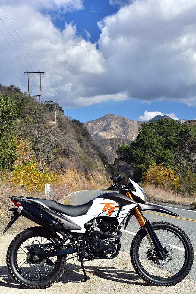

The title says it all, folks! Me? I was out and about on the TT250 making a new video for all of you TT250 fans…you asked for more, and we aim to please! It’s a longer video, so check back later today or tonight and I’ll have it on the blog!
I just got home after 32 hours of travel from Singapore to So Cal. Wow, I’m beat. I’ll be in the plant tomorrow, though, and I’ll be providing more good info on Baja, the TT250, the 2016 RX3 arrivals, and more.
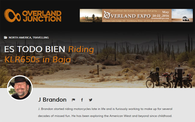
I’m catching up on my emails and more before I get some sleep (a lot of sleep, actually), and I was more than pleasantly surprised to see that my good buddy J has a new story out on Baja! You can read it here. As you know, J will be riding with us on our upcoming Baja expedition.
As long as I’m assigning homework, here are two more articles on Baja that I wrote for Motorcycle Classics Magazine: Baja by Motorcycle and San Felipe, Baja, Mexico. And, of course, there’s a whole chapter on the first CSC RX3 Baja ride in 5000 Miles At 8000 RPM (you can order that book from the link on the right). We’ll be hitting all of these good Baja spots (and more) on the next CSC run. I can’t wait.
Imagine that, all you CSC RX3 Baja riders: You’ll be riding with two published writers on our next Baja ride, and it’s less than 3 weeks away!
I promised a few photos from Singapore, and I like to keep my promises. Ah, where to begin…
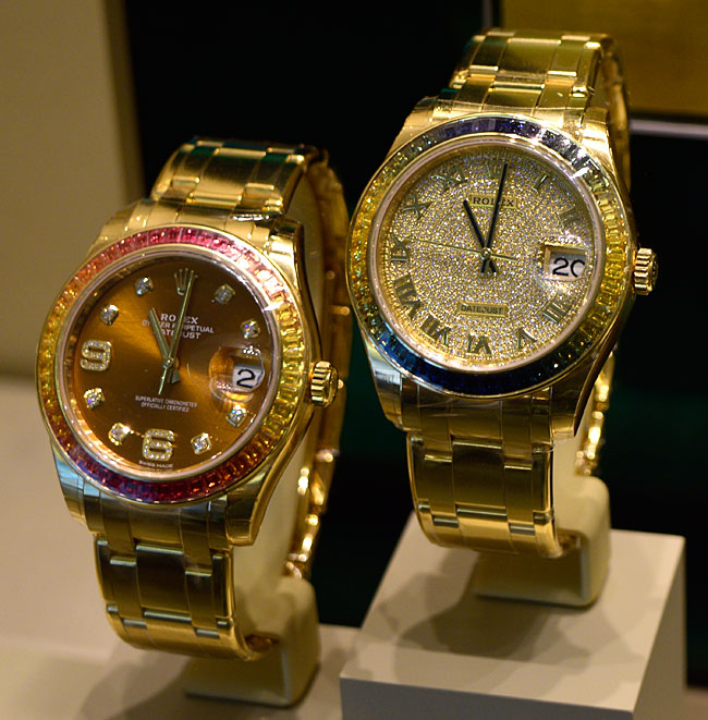
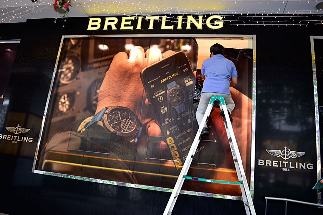
My impression is that Singapore is a very wealthy country, and it’s easy to speak with folks here. Everybody speaks English, so that’s made it very easy for me. I’m staying in a nice hotel on Orchard Road, which seems to be the Singaporean version of Rodeo Drive. There’s a lot of money over here, folks, and the place is spotless. The stores, for the most part, are the same ones we have in the US, and they seem to be very high end. I’ve seen more fancy watch stores along Orchard Road then I’ve ever seen anywhere else.
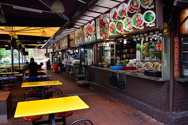
There are exotic restaurants and there are the standard ones we are used to seeing. It felt a little weird flying to the other side of the world and seeing these…
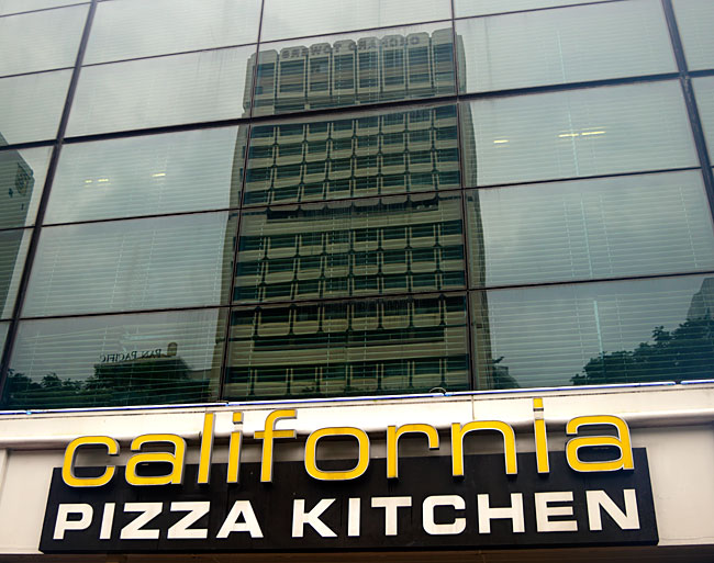
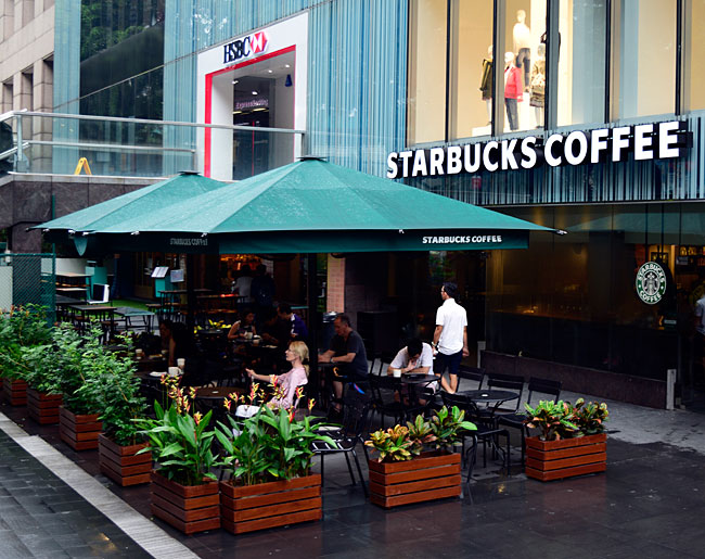

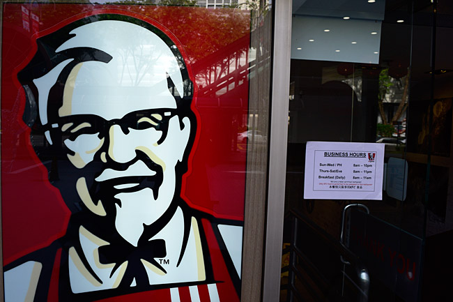
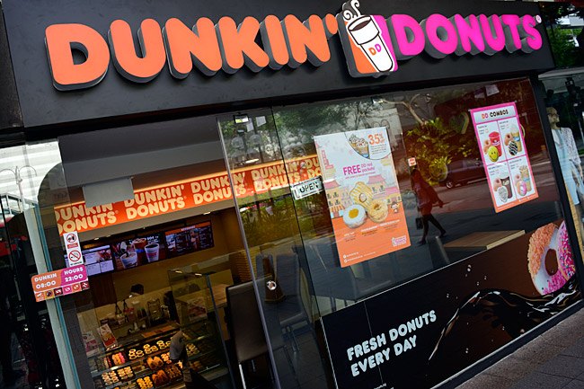
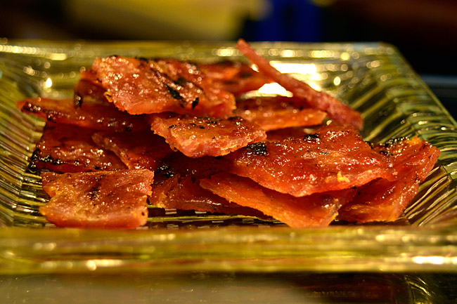
There are quite a few restaurants and that means you can have just about any kind of food you want. Based on Singapore’s location, you can enjoy Indian, Middle Eastern, Chinese, and other ethnic cuisine. My hosts are taking me to a nice Chinese restaurant tomorrow, and I’m looking forward to it. It’s not the place you see below; I saw that one while I was walking around yesterday and I thought it would make a good shot. And the photo below it? Well, that’s candied pork…
Oh, and that high end shopping I mentioned…there’s sure a lot of that…


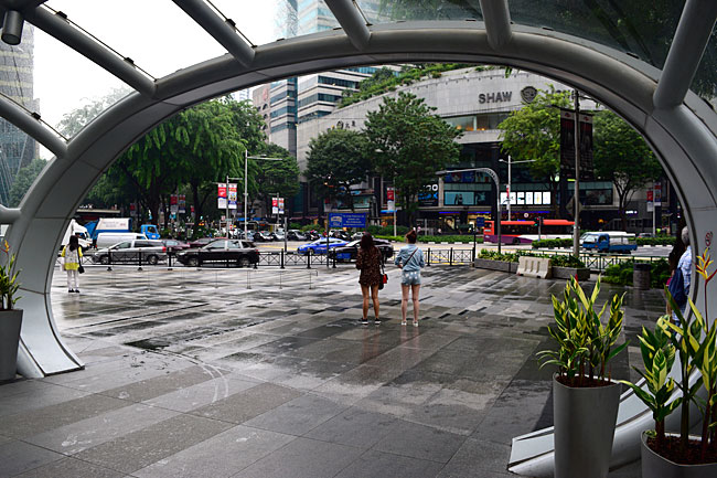
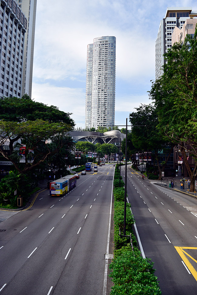
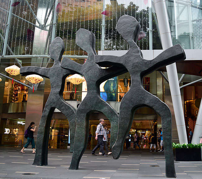
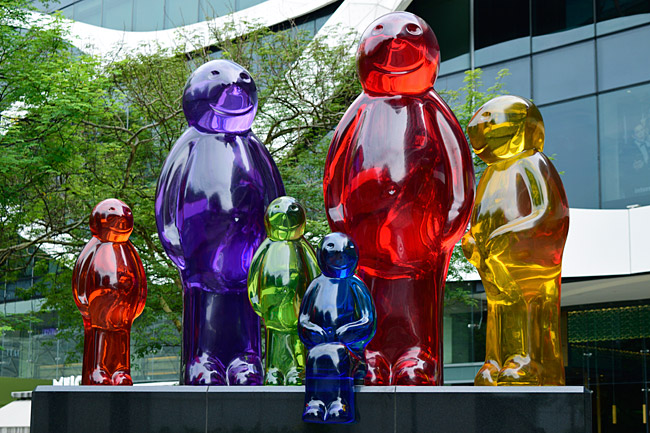
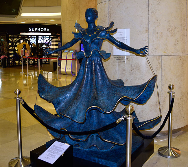
The section of Singapore I’m in is immaculate, and they have interesting art lining the streets and in the malls. When I say the place is immaculate, I mean exactly that…I don’t think I’ve ever been in a city anywhere this spotless.
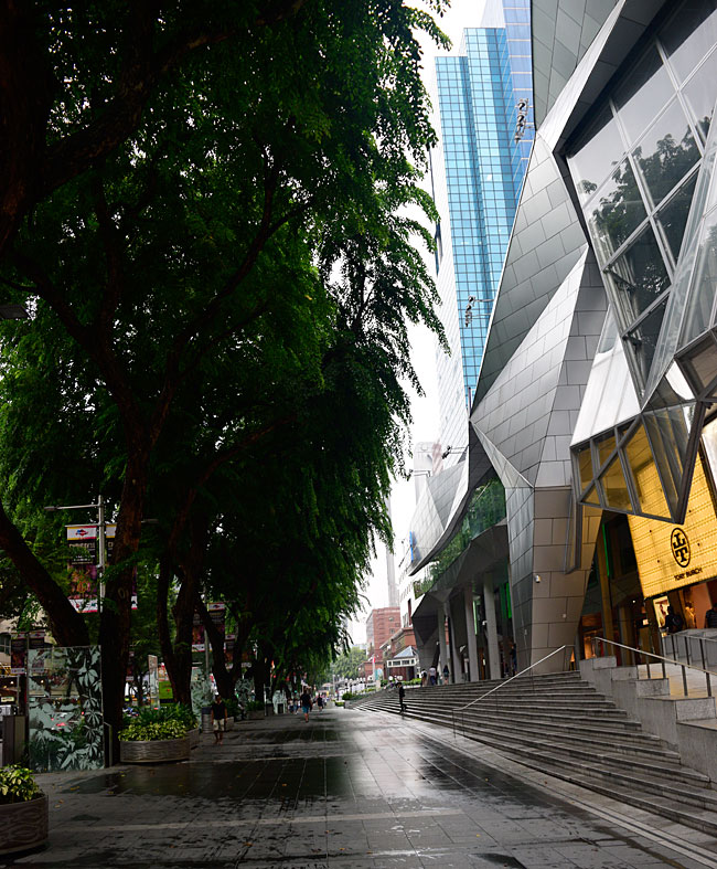

Yesterday (Sunday) was interesting. I walked the entire length of Orchard Road. Singaporeans love being out and about. They sure seem to like using their cell phone cameras.
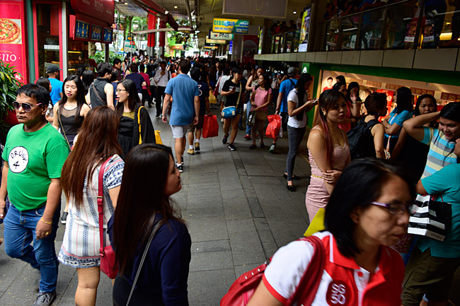
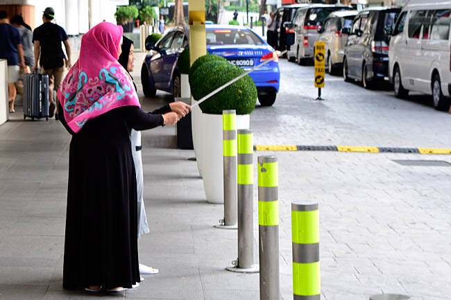
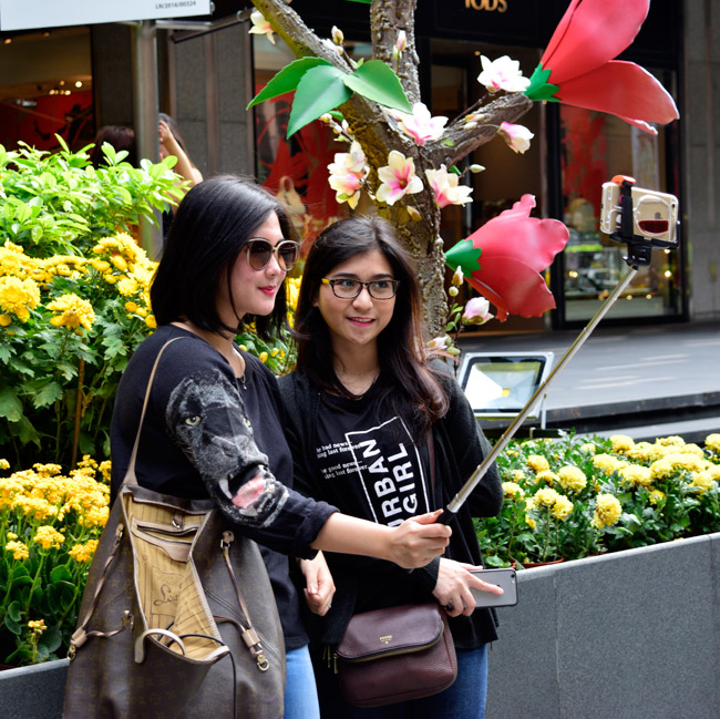
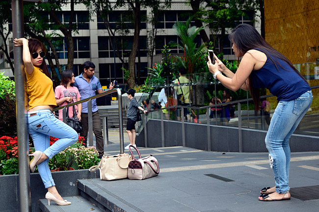
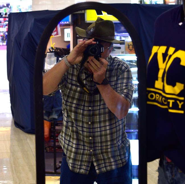
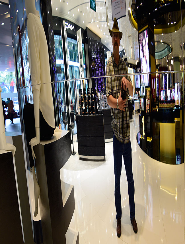
Seeing all those folks tripping shutters bumped me into the selfie mode…
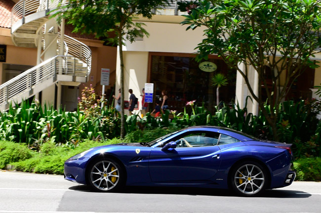
The transportation was interesting. As I said above, Orchard Road is Singapore’s Rodeo Drive, and the moto-exotica was impressive…

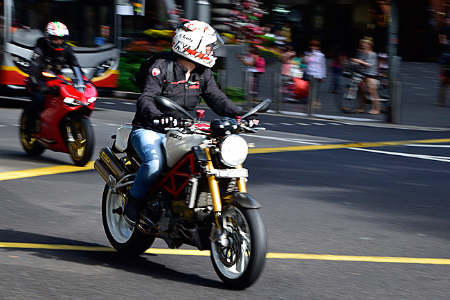
Surprisingly, there were not many motorcycles. The ratio of motorcycles to cars was about what you’d see in a US city. After Colombia and Bangkok, I guess I was expecting to see the same swarm of cycles I’d seen in those places, but Singapore is about like we are in that regard.
And folks, that’s about it. I’m going out for dinner in a bit, and I’m going “wings in the wells” for another 24 hours of flying the day after tomorrow. I’ve enjoyed Singapore.
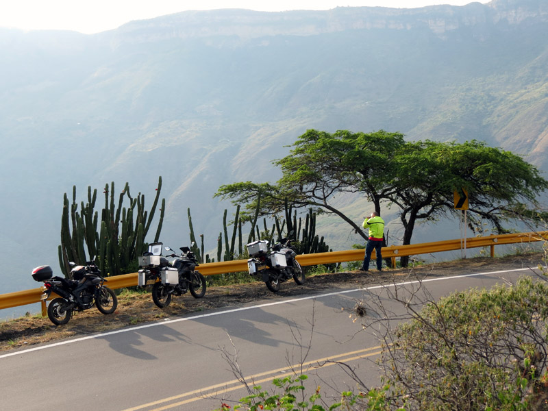
That’s me, taking a photo of the Chicamocha River Valley!
Folks, I had the time of my life riding an RX3 in Colombia. My good buddy Juan Carlos Posada (who was my guide on that trip) is now offering personally-guided tours in Coloombia just like the one I went on. I received this note from him this morning…
Joe:
Considering the current exchange rate of the dollar I can offer tours for $3,000. These will include 10 days on the motorcycle and 3 additional days in Colombia (for arrival and a rest at the end of the trip). I also want to offer a special discount to those who participate in the first tour. The price will be $ 2,500.
Thanks,
Juan
That is a tremendous deal, folks, and Juan isn’t just anybody. He’s Mr. Motorcycle in Colombia, and he’s the founder of DeMotos magazine. You might remember Juan from our Western America Adventure Ride. He’s the guy AKT Motos (the Colombian RX3 manufacturer) sent up here to ride with us, and he did a great piece on that trip in his magazine.
I know I sure had a whale of a time on my Colombian adventure ride. I think you will, too. It was incredible.
If you’re interested, you can reach Juan at juandemotos@hotmail.com.

Yours truly riding off the ferry on the way to Mompox
This is a first for me…a visit to Singapore!
The drive to the airport was the roughest part of the journey. It took 4 1/2 hours to get from my house to LAX yesterday (it was right through the middle of the morning commute and it rained all the way, which always degrades traffic conditions here in mostly-sunny So Cal). Next up was a 12-hour flight to Tokyo, then a 2 1/2 hour layover, and then another 7 hour flight to Singapore. Yikes. The good news is I arrived in Singapore at 2:00 a.m. local time, the airport was mostly empty, and getting through Customs was a snap.
The first leg (that 12-hour run to Tokyo) wasn’t a bad flight. It was on the new Boeing 787, and even though I was traveling steerage, it was comfortable. The 787 interior is huge, and the lighting was cool. Unlike any other flight I’ve ever been on, the little screen on the seat in front of me wasn’t so little. I watched four movies (they were all good) and ate two meals, and those 12 hours flew by quickly (if you’ll pardon the pun). The Martian (with Matt Damon) was great. Spot Light (about the Cardinal Law scandals in Boston) was similarly excellent. Spectre (the latest James Bond movie) wasn’t bad, although realistically that franchise went past its “sell by” date about 30 years ago. Then it was an old favorite, Saving Private Ryan, which is an absolutely fantastic movie that I’ve probably seen 10 times (and I’ll probably watch it again on the way home).
It’s mid-morning Saturday here (Friday night for you guys), and it’s raining in Singapore. Looks like the precipitation followed me to the other side of the world.
I had a nice note and a photo from my good buddy Duane when I checked my email at the hotel early this morning…
Duane, thanks for taking the time to write. We’ll get together for a ride real soon.
The Baja trip is shaping up nicely. We had another guy drop out and another one sign up, and the bottom line to that is we still have room for two more RX3 riders. This kind switching-and-dropping-and-adding is pretty much par for the course in the weeks before these kinds of rides. It’s happened on every Baja run I’ve ever done. On the CSC rides, though, I’ve been surprised at how many people who say they are going with us actually do. On earlier rides before we started doing the CSC adventure tours, we’d be lucky if one or two guys showed up the morning we left (regardless of how many people said they were going). RX3 riders are a much more committed group. It’s cool.
That’s it for now. I want to get out and explore Singapore, and I have two days to do it before the working part of this secret mission commences. Watch for photos…
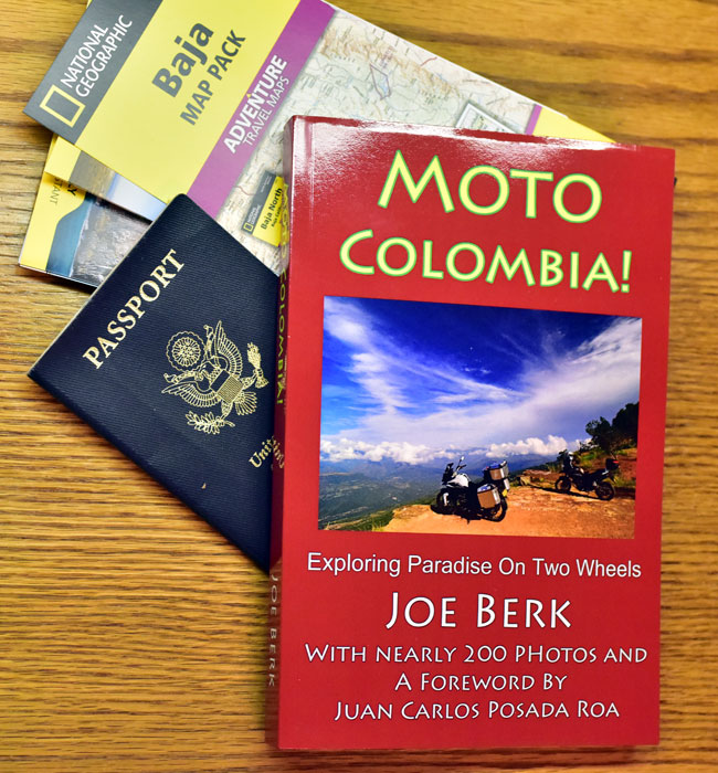
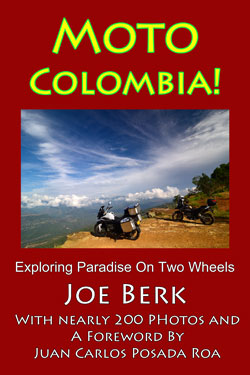
When I arrived home this evening, I had two things I ordered just a day or two ago…a set of maps for Baja and my very own copy of Moto Colombia! Amazon.com sure came through, and that’s a good thing. I’m getting on a airplane early tomorrow headed west across the Pacific. I’ll be in the air about 20 hours, and I wanted to have something to read (and now I do). Say what you will, but those folks at Amazon.com sure have their business model wired!
The Baja maps look pretty good. I know Baja well (I’ve been going down there about 25 years now), but the Auto Club quit making their Baja maps some time ago and these look to be a good replacement. We are at 14 people for the Baja ride as of today, and that leaves one opening.
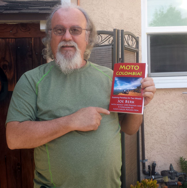
Moto Colombia! looks great. It’s awesome seeing something like this for the first time. I really like the way it turned out. My good buddies Juan and Carlos sure showed me a good time in Colombia. It was an amazing ride.
Watch for the photos from Singapore, folks…I’ll be posting them right here on the CSC blog!
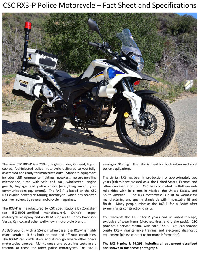
The RX3-P police motorcycle will be reporting for duty very shortly with a large police department (with over 300 sworn officers) for an extended evaluation period. We’re very excited about this, as is the department that will soon receive the RX3-P.
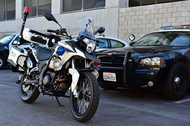
There’s more to follow, folks, and we’ll keep you updated. We’re not publicizing the department just yet because the police motorcycle business is fairly competitive.
More than a few folks have commented that a 250 is too small for police duty. Quite the opposite is the case, and there’s a good argument to be made that the current crop of US police bikes are actually too large. The Colombians, for example, use a 200cc Suzuki as their primary police bike (there’s a complete chapter in Moto Colombia! about Colombian police motorcycles). When I asked the Colombian motor officers if they knew about the much larger police bikes we typically use in the US, they laughed. They Colombians said they were well aware of them, but they were not suitable for offroad use or use in congested areas. The RX3-P doesn’t suffer from any of those deficiencies.
As always, keep an eye on the blog, folks. More to follow…
We sent around a confirmation email this week for the Baja run, and the good news is we still have room for two more riders. If you want to ride to Baja with us next month, shoot an email to me at jberk@cscmotorcycles.com.
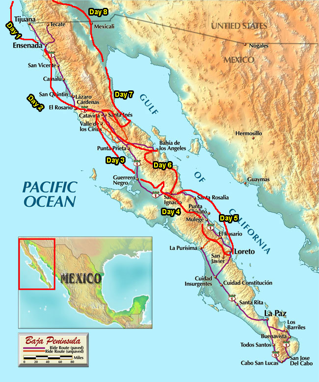
The CSC Baja 2 run will be a great ride, with whale watching, a run out to the San Jacinto shipwreck, the cave paintings, the missions, a bit of mild dirt riding through Coco’s Corner, La Bufadora, the wine country, the Vizcaino Desert, fish tacos, and more. We will ride along the Pacific Ocean and the Sea of Cortez, as well as Baja’s interior. I’m really looking forward to it.
More good news: Moto Colombia! is now available on Amazon. You can order it here!
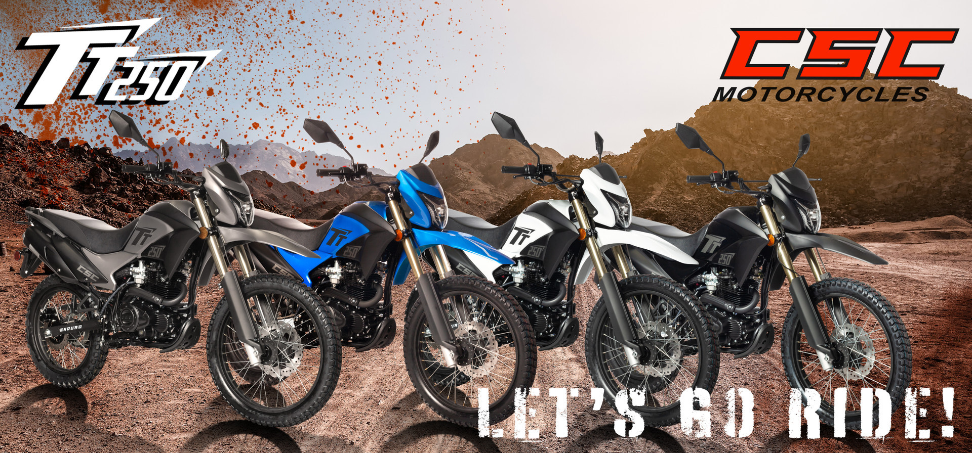
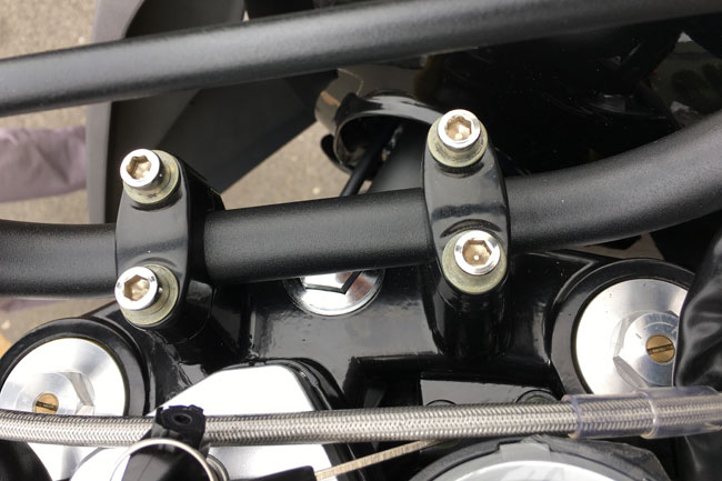
That’s it for now, folks. We are super busy at CSC, and we are looking forward to the arrival of the 2016 RX3s and TT250s. Oh, one last thing…the good guys at Zongshen sent us photos of the TT250s coming together. Check out the adjustable front suspension and the braided stainless steel brake lines on the TT250s!
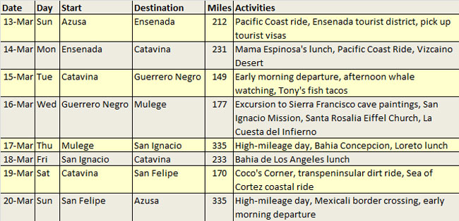
Folks, I sent an email around a short while ago to the people who are on the Baja list asking that you confirm your participation. These are the folks I have listed who are going to Baja with us:
If you’re not on the list, you haven’t emailed me to say you are going. If you are on the above list and you are not going, please let me know (other people want to go and we’re holding the number constant).
Here’s our itinerary…
Let me know by 20 February. Please don’t call the plant to confirm or to ask questions about Baja (the guys in the plant are busy getting ready for the 2016 RX3s and TT250s); shoot an email to me at jberk@cscmotorcycles.com.
Folks, Moto Colombia!, the story about my recent 2600-kilometer adventure tour in the Colombian Andes, is available now!
It was a ton of fun tearing around the twisties and the dirt roads in Colombia with my very capable motorcycling compadres Juan and Carlos showing me the way. It was the ride of a lifetime and you can read all about it now.
As I’m sipping a cup of delightful Colombian coffee this fine morning back here in southern California, I’m not sure what I enjoyed more: The actual ride through Colombia, or writing Moto Colombia!
This latest book has 200 photos and 62,000 words in 270 pages, with a foreword by my good buddy and DeMotos editor Juan Carlos, and I think it’s worth a read. If you enjoyed 5000 Miles At 8000 RPM (and the Amazon.com comments and your emails tell me you did), you’re going to want to read Moto Colombia!
Oh, I almost forgot: You can order your copy of Moto Colombia here!
 SG250 San Gabriel Cafe Racer
 TT250 Enduro