“A home run.”
“A 35 when evaluated on a scale of 1 to 10.”
“A dramatic increase in stopping power.”
“Everybody will want one of these.”
These are the ways I described our new 11.5-inch front rotor high performance brake kit after Gerry installed it on my RX3 this weekend. Mind you, I didn’t think the stock front brake was lacking. The stock RX3 front brake is about the same as the front brake on my KLR 650 or my old Harley Softail.
This new front brake, though, is phenomenal.

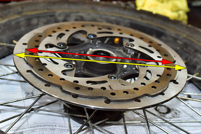
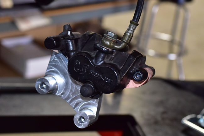
Take a look at this. The photo below shows the increase in diameter when going to the new front brake kit. The rotor jumps up to 11.5 inches in diameter and it increases in thickness from 4mm to 5mm. The rotor is high performance stainless steel, and you get a set of DP sintered pads with the package. We also include the new aircraft-grade billet aluminum caliper carrier (required for the larger diameter rotor) and a set of Allen bolts to mount the rotor to your hub. In short, the new kit includes everything you need to set up your RX3 to stop on a dime and give you 9 cents change!
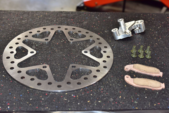
Here’s what you get: The new rotor, a set of rotor bolts, the caliper carrier, and the DP sintered brake pads. It’s $299.95 and you can get it by ordering it on our website, or by calling Ryan at 909 445 0900.
This tutorial shows you how to install the new front brake on your motorcycle. I need to warn you in advance, though…you will be tempted, but no stoppies or stunting allowed!
You’ll want to start by removing the front wheel (please refer to our RX3 front wheel removal tutorial) and the front brake caliper (please refer to our RX3 brake maintenance tutorial). Don’t disconnect the hydraulic line to the front caliper; it’s not necessary to do that.
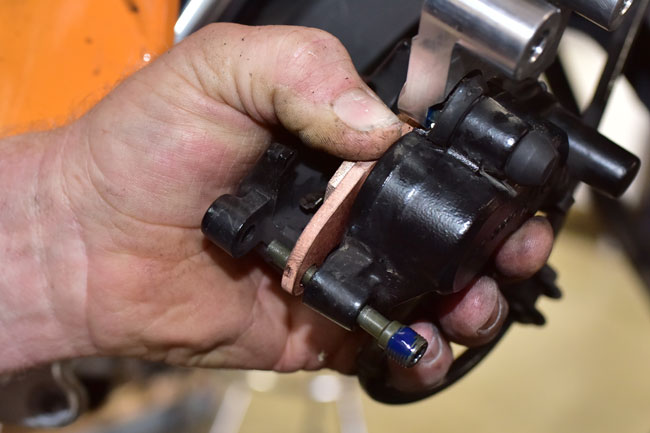
Remove the front brake caliper pin.
Remove the old brake pads.

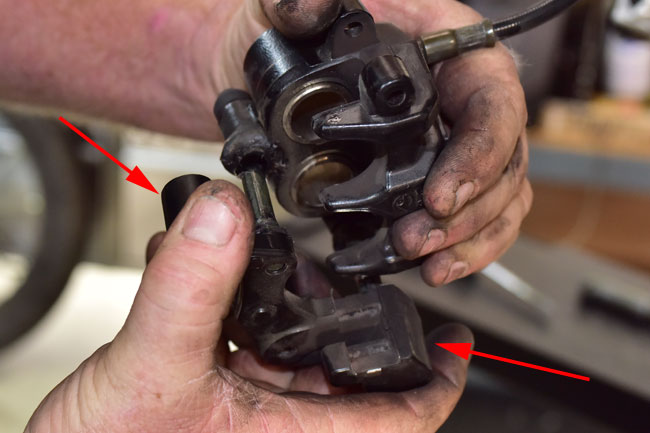
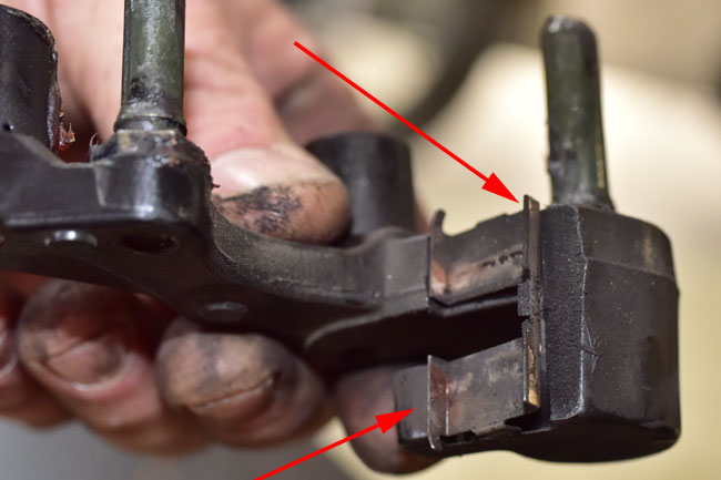
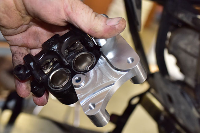
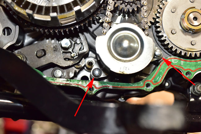
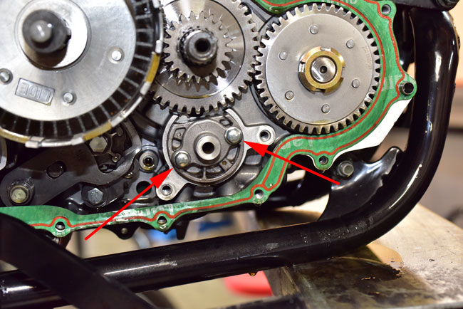
Remove the caliper mount (it’s the part the red arrows point to).
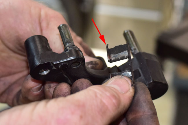
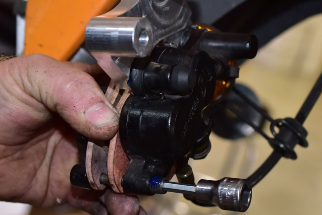
Remove the caliper clip. You’ll want to clean that part and set it aside. We’re going to reuse it.
Use a suitable solvent to clean the clip.

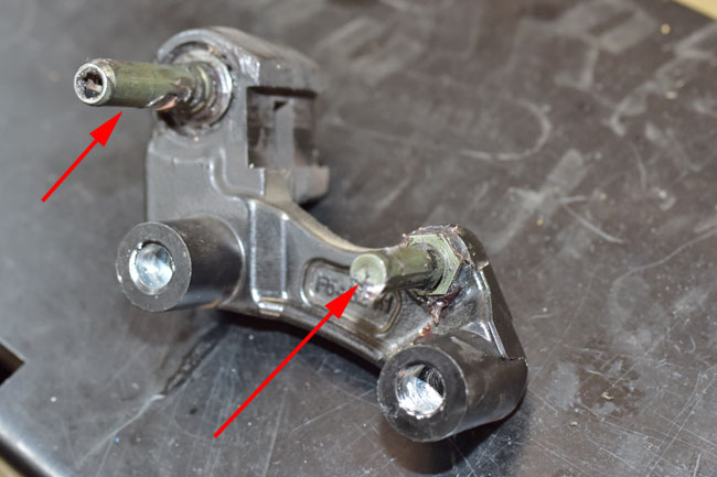
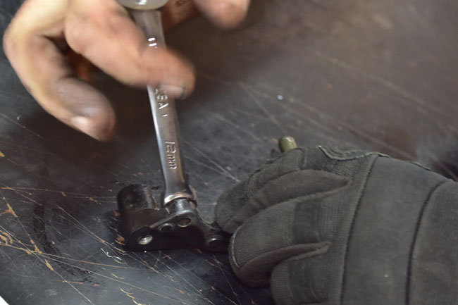
We are going to remove the threaded pins from the caliper mount that the caliper translates on. They are Loctited in place, so we have to heat the caliper mount to allow removing the pins.
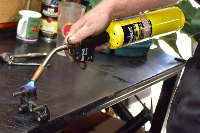
When you heat the caliper mount, don’t overdo it. You can use a torch or a heat gun. The trick is to get the caliper mount up to about 250 degrees Fahrenheit. Do one pin at a time.
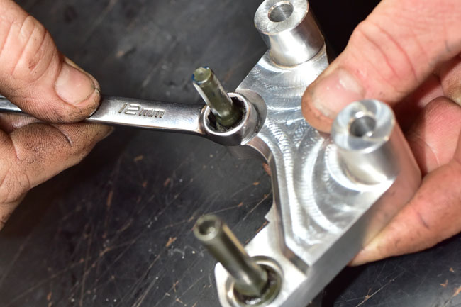
One pin is removed with a 12mm wrench. Be careful not to burn yourself.
The other pin is removed with a 6mm Allen wrench.

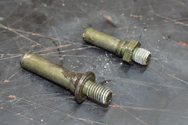
They will be pretty funky when you take them out of the caliper mount, so clean them with solvent.
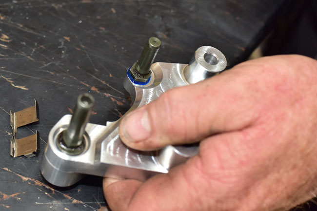
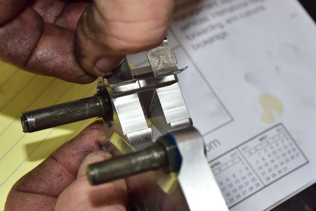
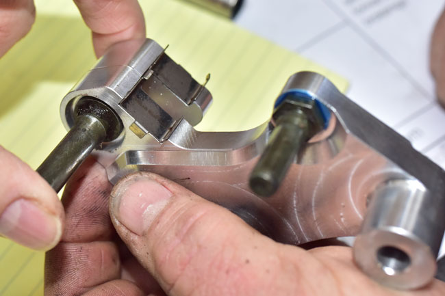
We are going to replace the old caliper mount with the new billet caliper mount.

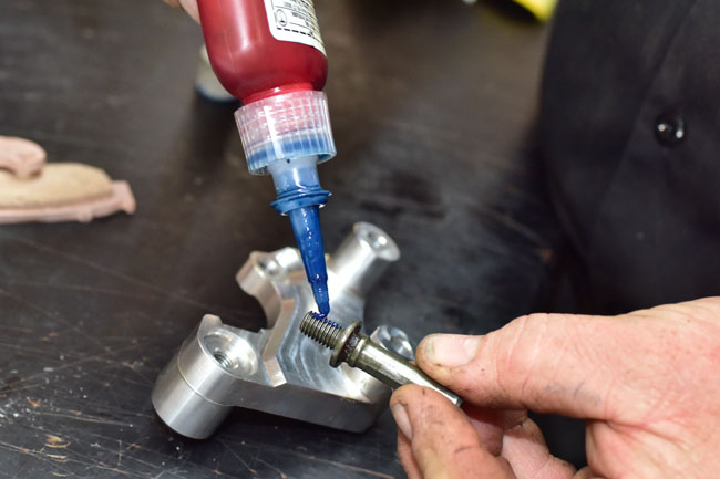
Install the caliper mount pins in the new caliper mount. Use blue Loctite.
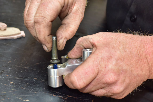
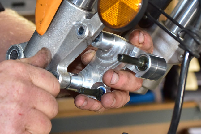
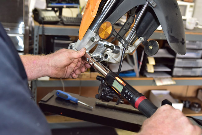
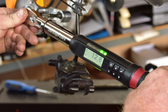
Temporarily install the caliper mount on the left front fork lower. We’re only doing this to allow torqueing the caliper pins to the correct torque. Torque the caliper pins to 25 N-m.
Remove the caliper mount from the front fork and install the clip. Note the clip’s orientation.
Apply and distribute a light coat of grease on the caliper pins.
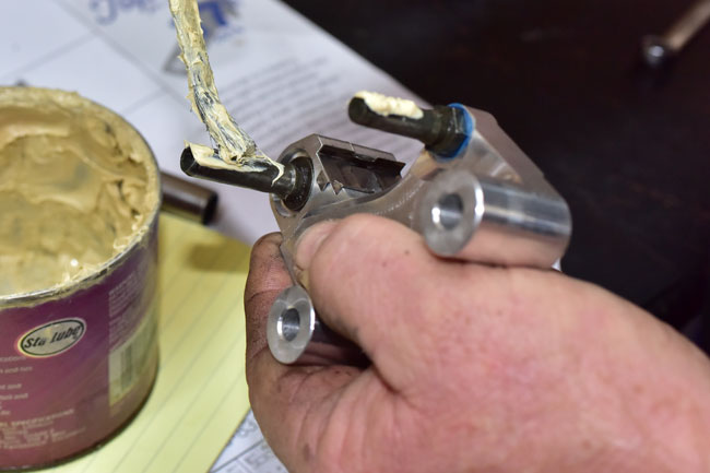
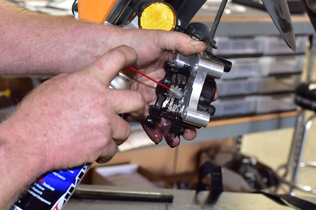
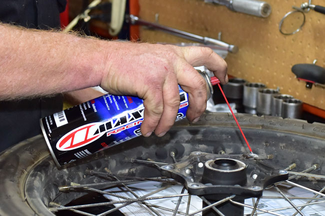
Slide the caliper onto the caliper mount. Use a spray solvent to remove any dirt from the caliper spring, as shown in the photo below.
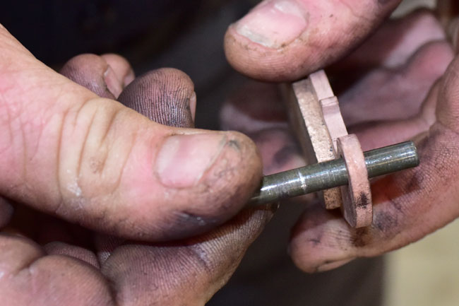
Check the brake pads on the brake pad pin to make sure they translate freely. Replace the brake pad pin if it is worn or if it has significant surface discontinuities.
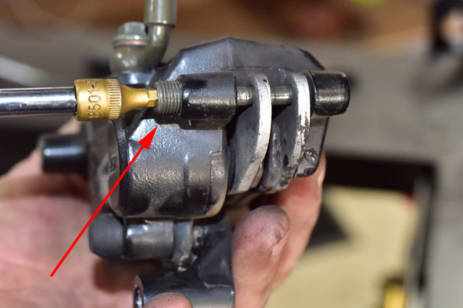
Apply blue Loctite to the brake pad pin as shown below.

Run the pin partly into the caliper and install the brake pads. The pin fits through the hole in each of the two brake pads.

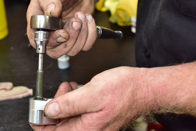
Screw the pin into the caliper using an Allen wrench or socket
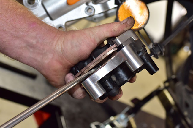
Force the brake pads apart with a large flat blade screwdriver. Use caution to not damage the brake pad surfaces.
At this point, allow the caliper to hang from the hydraulic brake line.
Or next steps involve removing the stock brake rotor. This part is secured by 6 Allen bolts. It is relatively easy to strip the Allen head in these bolts. That’s one of the reasons we provide six new Allen bolts with this kit. If you strip the Allen head, you’ll have the new Allen bolts included with the kit that you can use, but you’ll still have to get the old Allen bolt out. That usually involves cutting metal and a lot of cussing. Your best bet is to do as we advise here to get the old Allen bolts out.
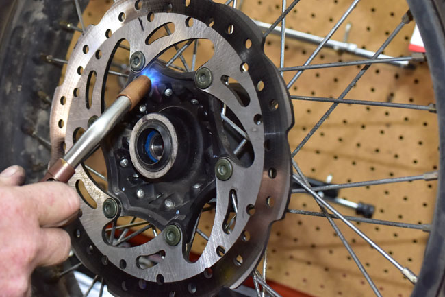
The bolts are Loctited in place. Heat the wheel hub just like we heated the caliper mount earlier. Heat one or two bolts at a time; do not attempt to heat the entire hub. If you use a torch, take care not to heat the spokes or you will ruin them. Heat the rotor Allen bolts to about 250 degrees Fahrenheit. Use a sharp Allen wrench to remove them.
After you have removed the Allen bolts, diligently clean the rotor mounting surface and the threads. You’ll want to remove all of the blue Loctite residue you see in the photo below.

We start this cleaning process with a solvent.
Gerry then uses a razor to remove the residue.
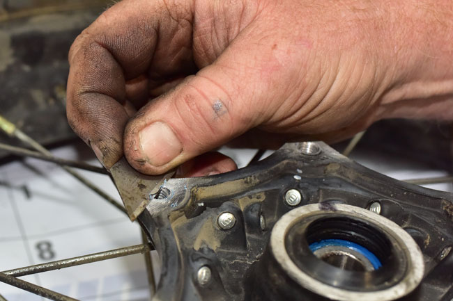
Gerry then touches up the rotor/hub interface area to assure there are no high spots. This is an important part of the process. You may have read about front brake pulsation that may occur on some RX3 motorcycles; in our experience, this is typically caused by an uneven rotor/hub interface surface.
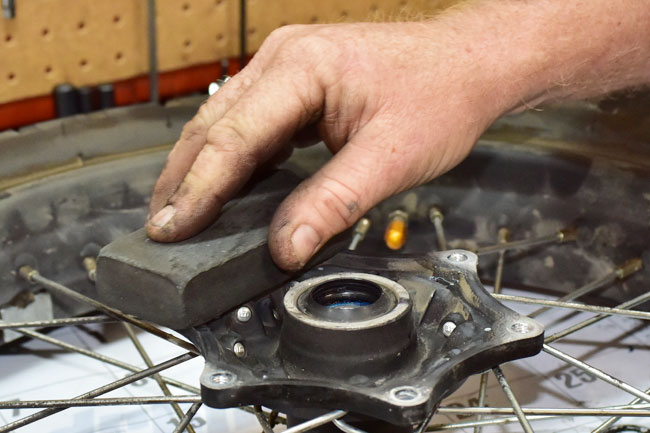
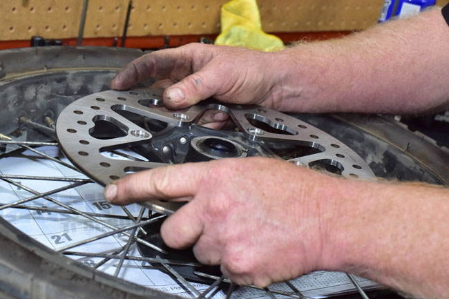
Place the rotor on the hub. Check to see there is no rocking due to unevenness in the rotor/hub interface area.
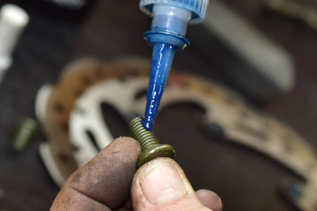
Apply blue Loctite to the rotor mounting bolts.
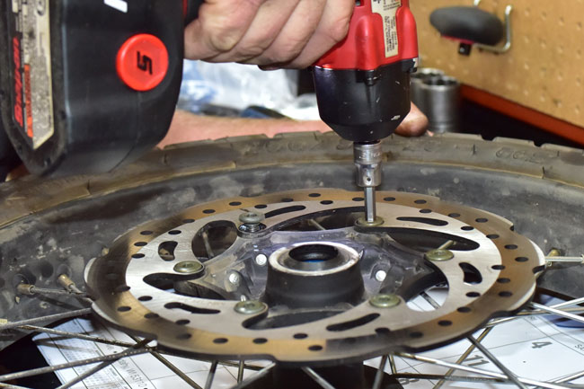
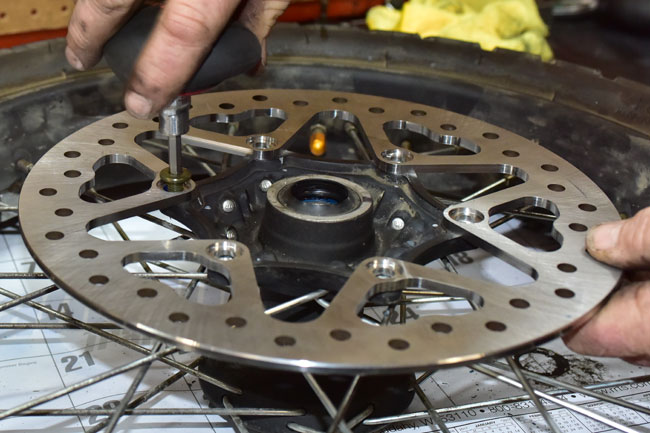
Install the rotor mounting bolts, torqueing them lightly at first to assure that the bolts’ shoulders are seated within the rotor mounting holes.
Reinstall the front wheel as described in the RX3 front wheel removal tutorial.
When we do this, we replace the original shouldered front axle pinch bolts with fully threaded Allen bolts. They look better and we have found that these allow for more a more controlled torque application. These bolts should be torqued to 20 N-m. Do not over torque these bolts. The intent is to pinch the front axle. Do not attempt to remove the gap in the right fork lower casting.

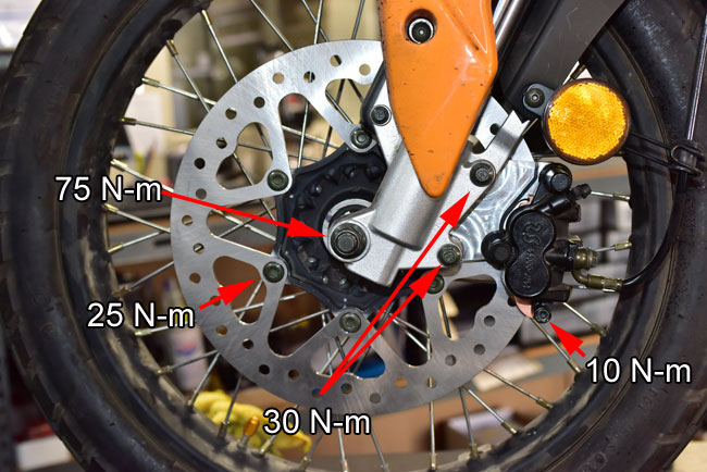
At this point, you should torque all of the bolts on the left side of the front wheel.
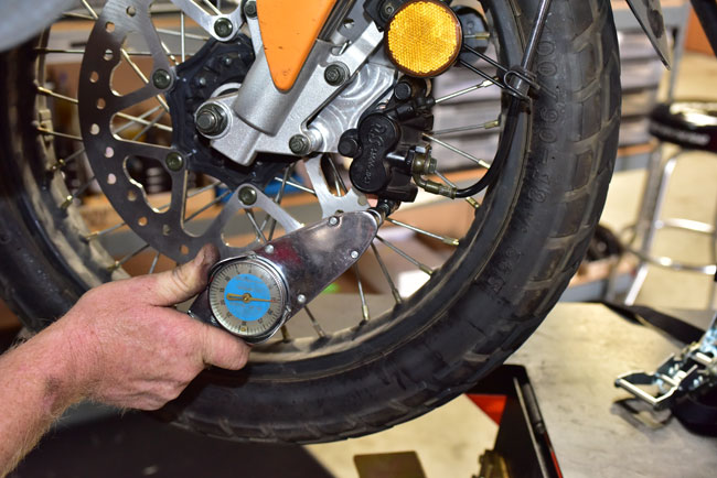
The torque values are shown below. Use a criss-cross pattern when torqueing the rotor bolts.
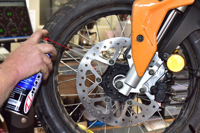
Clean the rotor with a solvent and wipe it clean.
Take care when first riding the motorcycle after installing the new front brake kit. You will want to properly bed the new pads on the new rotor, so stop with light braking force a few times and gradually build up to full brake applications. The front brake will be substantially stronger than the stock brake, so practice stopping with it to get a feel for the new brake’s power.


 TT250 Enduro
 SG250 San Gabriel Cafe Racer